Nissan Juke Service and Repair Manual : ECU diagnosis information
ECM
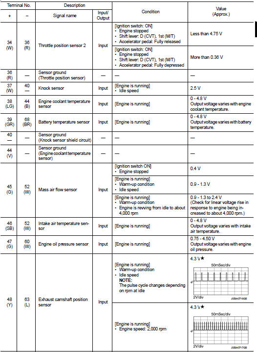
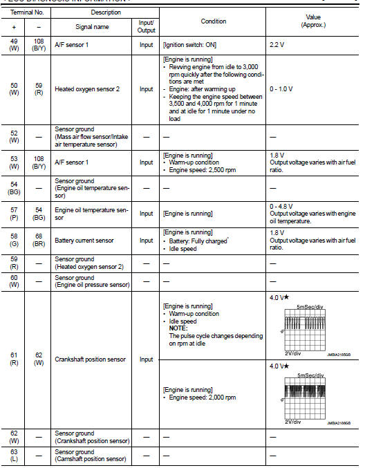
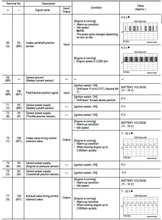
Reference Value
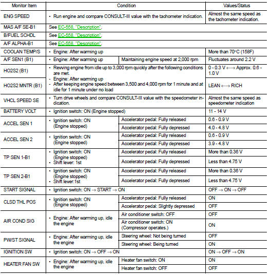
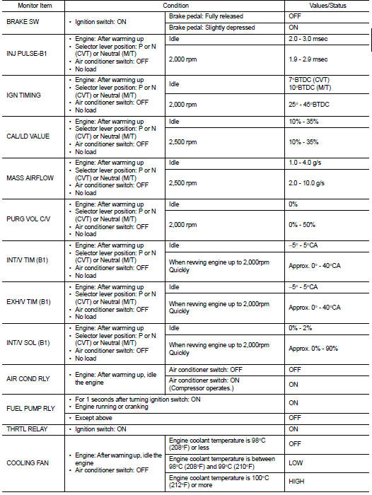
VALUES ON THE DIAGNOSIS TOOL
Remarks:
‚ÄĘ Specification data are reference values.
‚ÄĘ Specification data are output/input values which are detected or supplied by the ECM at the connector.
*Specification data may not be directly related to their components signals/values/operations.
i.e. Adjust ignition timing with a timing light before monitoring IGN TIMING, because the monitor may show the specification data in spite of the ignition timing not being adjusted to the specification data. This IGN TIMING monitors the data calculated by the ECM according to the signals input from the camshaft position sensor and other ignition timing related sensors.


*: Accelerator pedal position sensor 2 signal and throttle position sensor 2 signal are converted by ECM internally. Thus, they differ from ECM terminals voltage signal.
TERMINAL LAYOUT
PHYSICAL VALUES
NOTE
:
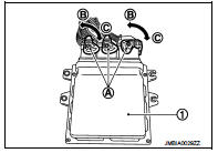
‚ÄĘ ECM is located in the engine room left side near battery.
‚ÄĘ When disconnecting ECM harness connector (A), loosen (C) it with levers as far as they will go as shown in the figure.
- ECM (1)
- Fasten (B)
‚ÄĘ Connect a break-out box and harness adapter between the ECM and ECM harness connector.
- Use extreme care not to touch 2 pins at one time.
- Data is for comparison and may not be exact.
‚ÄĘ Specification data are reference values and are measured between each terminals.
‚ÄĘ Pulse signal is measured by CONSULT-III.
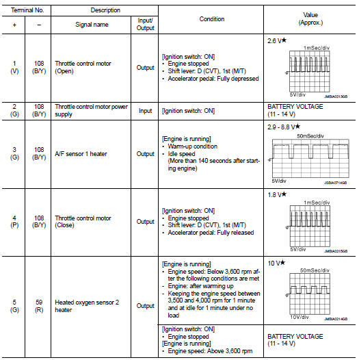


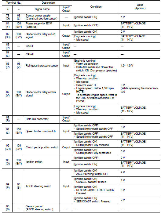

 : Average voltage for pulse
signal (Actual pulse signal can be confirmed by oscilloscope.)
*: Before measuring the terminal voltage, confirm that the battery is fully
charged. Refer to PG-111, "How to
Handle Battery".
Fail Safe
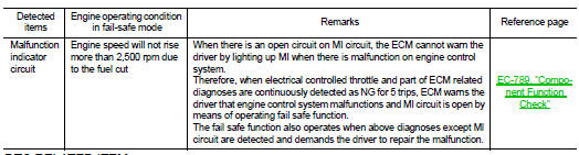
NON DTC RELATED ITEM
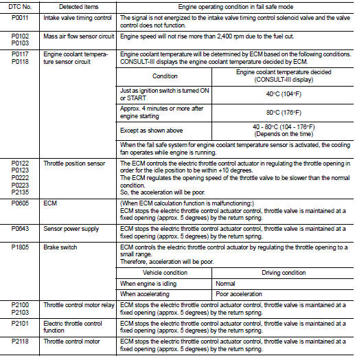
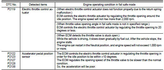
DTC RELATED ITEM
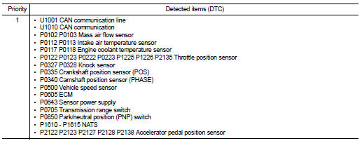
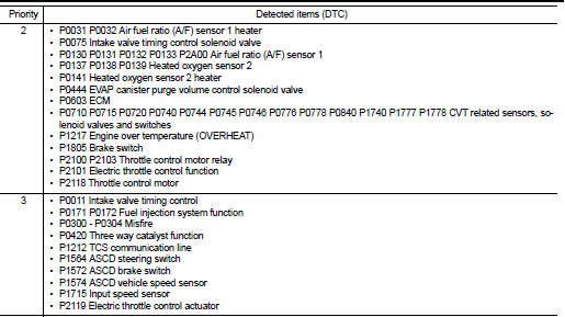
DTC Inspection Priority Chart
If some DTCs are displayed at the same time, perform inspections one by one based on the following priority chart.
DTC Index
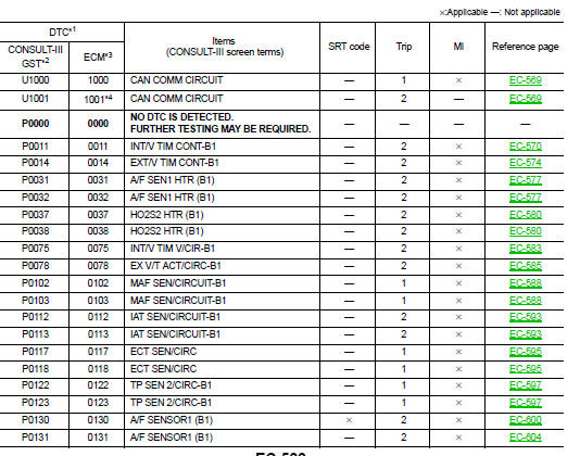
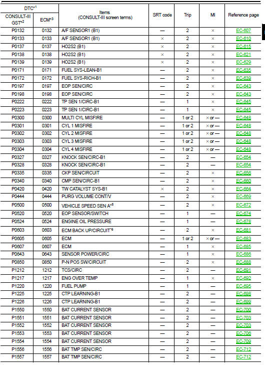
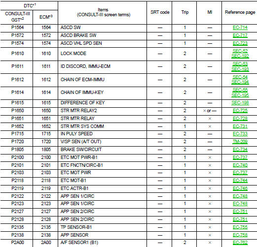
*1: 1st trip DTC No. is the same as DTC No.
*2: This number is prescribed by SAE J1979/ ISO 15031-5.
*3: In Diagnostic Test Mode II (Self-diagnostic results), this number is controlled by NISSAN.
*4: The troubleshooting for this DTC needs CONSULT-III.
*5: When the fail-safe operations for both self-diagnoses occur, the MI illuminates.
*6: This self-diagnosis is not for ECM power supply circuit, even though ‚ÄúECM BACK UP/CIRCUIT‚ÄĚ is displayed on CONSULT-III screen.
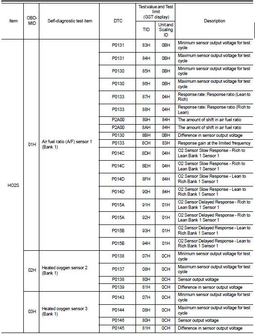
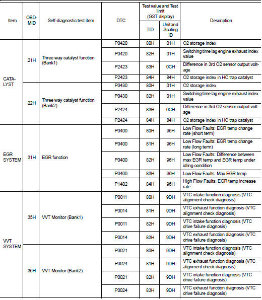
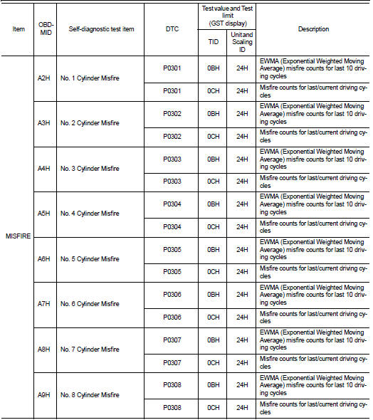
Test Value and Test Limit
The following is the information specified in Service $06 of SAE J1979/ISO 15031-5.
The test value is a parameter used to determine whether a system/circuit diagnostic test is OK or NG while being monitored by the ECM during self-diagnosis. The test limit is a reference value which is specified as the maximum or minimum value and is compared with the test value being monitored.
These data (test value and test limit) are specified by On Board Monitor ID (OBDMID), Test ID (TID), Unit and Scaling ID and can be displayed on the GST screen.
The items of the test value and test limit will be displayed with GST screen which items are provided by the ECM. (e.g., if bank 2 is not applied on this vehicle, only the items of bank 1 are displayed)


 Diagnosis system (ECM)
Diagnosis description : 1st Trip Detection Logic and Two Trip Detection
Logic
When a malfunction is detected for the first time, 1st trip DTC and 1st trip
Freeze Frame data are stored in the
ECM ...
 Wiring diagram
Engine control system
Wiring Diagram
For connector terminal arrangements, harness layouts, and alphabets in a
(option abbreviation; if not
described in wiring diagram), refer to GI-12, "Conn ...
Other materials:
Hood switch
Component Function Check
1.CHECK FUNCTION
1. Select ‚ÄúHOOD SW‚ÄĚ in ‚ÄúData Monitor‚ÄĚ mode of ‚ÄúIPDM E/R‚ÄĚ using CONSULT-III.
2. Check ‚ÄúHOOD SW‚ÄĚ indication under the following condition.
Is the indication normal?
YES >> Hood switch is OK.
NO >> Go to SEC-223, "Diag ...
Precaution Necessary for Steering Wheel Rotation after Battery Disconnect
NOTE:
‚ÄĘ Before removing and installing any control units, first turn the ignition
switch to the LOCK position, then disconnect
both battery cables.
‚ÄĘ After finishing work, confirm that all control unit connectors are connected
properly, then re-connect both
battery cables.
‚ÄĘ Always us ...
B1066, B1071 passenger air bag module
DTC Logic
DTC DETECTION LOGIC
DTC CONFIRMATION PROCEDURE
1.CHECK SELF-DIAG RESULT
With CONSULT-III
1. Turn ignition switch ON.
2. Perform ‚ÄúSelf Diagnostic Result‚ÄĚ mode of ‚ÄúAIR BAG‚ÄĚ using CONSULT-III.
Without CONSULT-III
1. Turn ignition switch ON.
2. Check the air bag warning la ...
