Nissan Juke Service and Repair Manual : Cooling fan
Diagnosis Procedure
1.CHECK GROUND CONNECTION
1. Turn ignition switch OFF.
2. Check ground connection E38. Refer to Ground Inspection in GI-44, "Circuit Inspection".
Is the inspection result normal? YES >> GO TO 2.
NO >> Repair or replace ground connection.
2.CHECK COOLING FAN MOTOR CIRCUIT
1. Disconnect cooling fan motor harness connector.
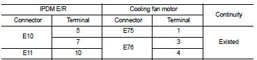
2. Check the continuity between IPDM E/R harness connector and cooling fan motor harness connector.
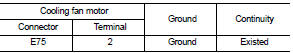
3. Check the continuity between cooling fan motor harness connector and ground.
4. Also check harness for short to ground and short to power.
YES or NO YES >> GO TO 4.
NO >> GO TO 3.
3.DETECT MALFUNCTIONING PART
Check the following.
• Harness for open or short between cooling fan motor and IPDM E/R • Harness for open or short between cooling fan motor and ground
>> Repair open circuit or short to ground or short to power in harness or connectors.
4.CHECK COOLING FAN MOTOR
Refer to EC-1015, "Component Inspection".
YES or NO YES >> GO TO 5.
NO >> Replace cooling fan motor.
5.CHECK INTERMITTENT INCIDENT
Perform GI-42, "Intermittent Incident".
YES or NO YES >> Replace IPDM E/R. Refer to PCS-34, "Exploded View" (WITH I-KEY) or PCS-63, "Exploded View" (WITHOUT I-KEY).
NO >> Repair or replace harness or connector.
Component Inspection
1.CHECK COOLING FAN MOTOR
1. Turn ignition switch OFF.
2. Disconnect cooling fan motor harness connector E75 and E76.
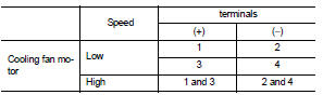
3. Supply cooling fan motor terminals with battery voltage and check operation.
Is the inspection result normal? YES >> INSPECTION END
NO >> Replace cooling fan motor.
 CAN communication circuit
Description
CAN (Controller Area Network) is a serial communication line for real time
application. It is an on-vehicle multiplex
communication line with high data communication speed and excellen ...
 Information display (ASCD)
Component Function Check
1.CHECK INFORMATION DISPLAY
1. Start engine.
2. Press ASCD MAIN switch.
3. Drive the vehicle at more than 30 km/h (20 MPH)
CAUTION:
Always drive vehicle at a safe speed. ...
Other materials:
Front fog lamp circuit
Component Function Check
1.CHECK FRONT FOG LAMP OPERATION
CONSULT-III ACTIVE TEST
1. Select “EXTERNAL LAMPS” of IPDM E/R active test item.
2. With operating the test items, check that the front fog lamp is turned ON.
Fog : Front fog lamp ON
Off : Front fog lamp OFF
Is the measurement norm ...
Diagnosis system (IPDM E/R)
With intelligent key
WITH INTELLIGENT KEY : Diagnosis Description
AUTO ACTIVE TEST
Description
In auto active test mode, the IPDM E/R sends a drive signal to the following
systems to check their operation.
• Oil pressure warning lamp (only for K9K engine models)
• Rear window defogger
...
Front oil seal
Exploded View
1. Rear final drive assembly
2. Front oil seal
3. Companion flange
4. Companion flange lock nut
A. Oil seal lip
: Vehicle front
: N·m (kg-m, ft-lb)
: Never reuse parts
: Apply multi purpose grease
: Apply gear oil.
Removal and Installation
REMOVAL
CAUTION:
Verify ide ...
