Nissan Juke Service and Repair Manual : Control cable
Exploded View
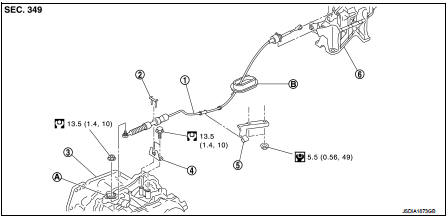
1. Control cable
2. Lock plate
3. Transaxle assembly
4. Bracket A
5. Bracket B
6. CVT shift selector assembly
A: Manual lever B: Grommet
 : N·m (kg-m, ft-lb)
 : N·m (kg-m, in-lb)
Removal and Installation
INSTALLATION
CAUTION:
Always apply the parking brake before performing removal and installation.
1. Remove the battery. Refer to PG-124, "Removal and Installation".
2. Remove the control cable from the CVT shift selector assembly. Refer to TM-270, "Removal and Installation".
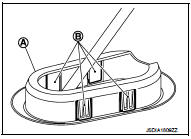
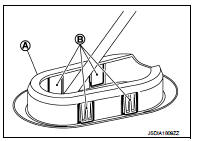
3. Disengage the pawls (B) of the grommet (A), and pull downwards to remove.
4. Remove the control cable installation nut from the manual lever.
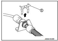
5. Remove the lock plate (1).
6. Remove center muffler from the mounting rubber and lower the center muffler downward. Refer to EX-6, "Removal and Installation".
7. Lift up the heat plate.
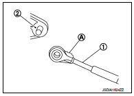
8. Remove the control cable (1) from the bracket (2).
 :Vehicle front
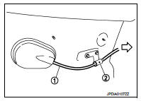
9. Remove the control cable from the vehicle.
10. Remove bracket.
INSTALLATION
Note the following, and install in the reverse order of removal.
• From below the vehicle, press the grommet (A) into place until the pawls (B) make a click sound.
CAUTION:
• Place the grommet on the floor, then fasten it in place from
below the vehicle.
• Check that pulling down on the grommet does not disconnect it.
• Pay attention to the following when connecting the control cable to the CVT shift selector.
1. When connecting the control cable (1) to the CVT shift selector assembly (2), face the grooved surface of the rib (A) up and insert the control cable until it stops.
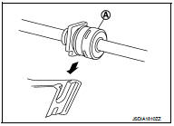
2. Install the socket (A) onto the CVT shift selector.
CAUTION:
• Place the socket onto the CVT shift lever, then fasten it in
place from above.
• Check that the pulling on the socket does not disconnect it.
Inspection
INSPECTION AFTER INSTALLATION
Check the CVT position. If a malfunction is found, adjust the CVT position. Refer to TM-194, "Inspection and Adjustment".
 CVT shift selector
Exploded View
1. Selector lever knob
2. Lock pin
3. Knob cover
4 Position indication panel
5. CVT shift selector assembly
6. CVT shift lock unit
7. Key interlock rod*
8. Indicator lamp
...
 Key interlock cable
Exploded View
1. CVT shift selector assembly
2. Key interlock cable
A: Key cylinder
B: Clip
C: Clip
Removal and Installation
REMOVAL
CAUTION:
Always apply the parking brake before perfor ...
Other materials:
Symptom diagnosis
COMBINATION SWITCH SYSTEM SYMPTOMS
Symptom Table
1. Perform “Data Monitor” of CONSULT-III to check for any malfunctioning
item.
2. Check the malfunction combinations.
3. Identify the malfunctioning part from the agreed combination and repair or
replace the part.
...
Unlock sensor
Component Function Check
1.CHECK FUNCTION
1. Select “DOOR LOCK” of “BCM” using CONSULT-III.
2. Select “LOCK STATUS” in “DATA MONITOR” mode.
3. Check that the function operates normally according to the following
conditions.
Is the inspection result normal?
YES >> Unlo ...
Cargo cover (if so equipped)
WARNING
• Never put anything on the cargo cover, no matter how small. Any object on
it could cause an injury in an accident or sudden stop.
• Do not leave the cargo cover in the vehicle with it disengaged from the holder.
• The child restraint top tether strap may be damaged by contact wi ...
