Nissan Juke Service and Repair Manual : Compressor dose dot operate
Description
SYMPTOM
Compressor dose not operate.
Diagnosis Procedure
NOTE
:
• Perform self-diagnoses with CONSULT-III before performing symptom diagnosis.
If any DTC is detected,
perform the corresponding diagnosis.
• Check that refrigerant is enclosed in cooler cycle normally. If refrigerant amount is shortage from proper amount, perform the inspection of refrigerant leakage.
1.CHECK MAGNET CLUTCH OPERATION
Check magnet clutch. Refer to HAC-175, "Component Function Check".
Does it operate normally? YES >> GO TO 2.
NO >> Repair or replace malfunctioning parts.
2.CHECK REFRIGERANT PRESSURE SENSOR
Check refrigerant pressure sensor. Refer to the following.
• HR16DE: Refer to EC-790, "Component Function Check".
• MR16DDT: Refer to EC-423, "Component Function Check".
• K9K: Refer to EC-960, "DTC Logic".
Is the inspection result normal? YES >> GO TO 3.
NO >> Repair or replace malfunctioning parts.
3.CHECK A/C ON SIGNAL
Check A/C ON signal. Refer to HAC-166, "Component Function Check".
Is inspection result normal? YES >> GO TO 4.
NO >> Repair or replace malfunctioning parts.
4.CHECK BLOWER FAN ON SIGNAL
Check blower fan ON signal. Refer to HAC-168, "Component Function Check".
Is the inspection result normal? YES >> GO TO 5.
NO >> Repair or replace malfunctioning parts 5.CHECK BCM OUTPUT SIGNAL
 With CONSULT-III
1. Select “DATA MONITOR” mode of “ECM” using CONSULT-III.
2. Select “AIR COND SIG” and “HEATER FAN SW”, and check status under the following conditions.
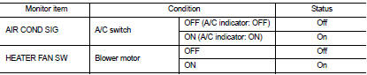
Is the inspection result normal? YES >> Replace IPDM E/R. Refer to PCS-34, "Removal and Installation" (with Intelligent Key) or PCS-63, "Removal and Installation" (without Intelligent Key).
NO >> Replace BCM. Refer to BCS-93, "Removal and Installation" (with Intelligent Key) or BCS-161, "Removal and Installation" (without Intelligent Key).
 Insufficient heating
Description
Symptom
• Insufficient heating
• No warm air comes out. (Air flow volume is normal.)
Diagnosis Procedure
NOTE:
Perform self-diagnoses with CONSULT-III before performing symptom d ...

Other materials:
Front fender
Exploded View
1. Front fender assembly
2. Front fender stiffener
: Vehicle front
Removal and Installation
REMOVAL
1. Remove front fillet molding. Refer to EXT-26, "FRONT FILLET MOLDING :
Removal and Installation".
2. Remove front bumper fascia assembly. Refer to EXT-13, "R ...
Brake pad wear warning
The disc brake pads have audible wear warnings.
When a brake pad requires replacement, it will make a high pitched scraping sound
when the vehicle is in motion. This scraping sound will first occur only when the
brake pedal is depressed. After more wear of the brake pad, the sound will always
...
P159A, P159C, P159D G sensor
For M/T models : DTC Logic
DTC DETECTION LOGIC
DTC CONFIRMATION PROCEDURE
1.PRECONDITIONING
If DTC Confirmation Procedure has been previously conducted, always perform
the following procedure
before conducting the next test.
1. Turn ignition switch OFF and wait at least 10 seconds.
2. T ...
