Nissan Juke Service and Repair Manual : Compressor dose dot operate
Description
SYMPTOM
Compressor dose not operate.
Diagnosis Procedure
NOTE
:
• Perform self-diagnoses with CONSULT-III before performing symptom diagnosis.
If any DTC is detected,
perform the corresponding diagnosis.
• Check that refrigerant is enclosed in cooler cycle normally. If refrigerant amount is shortage from proper amount, perform the inspection of refrigerant leakage.
1.CHECK MAGNET CLUTCH OPERATION
Check magnet clutch. Refer to HAC-83, "Component Function Check".
Does it operate normally? YES >> GO TO 2.
NO >> Repair or replace malfunctioning parts.
2.CHECK REFRIGERANT PRESSURE SENSOR
Check refrigerant pressure sensor. Refer to EC-423, "Component Function Check".
Is the inspection result normal? YES >> GO TO 3.
NO >> Repair or replace malfunctioning parts.
3.CHECK A/C ON SIGNAL
Check A/C ON signal. Refer to HAC-75, "Component Function Check".
Is inspection result normal? YES >> GO TO 4.
NO >> Repair or replace malfunctioning parts.
4.CHECK BLOWER FAN ON SIGNAL
Check blower fan ON signal. Refer to HAC-77, "Component Function Check".
Is the inspection result normal? YES >> GO TO 5.
NO >> Repair or replace malfunctioning parts 5.CHECK BCM OUTPUT SIGNAL
 With CONSULT-III
1. Select “DATA MONITOR” mode of “ECM” using CONSULT-III.
2. Select “AIR COND SIG” and “HEATER FAN SW”, and check status under the following conditions.
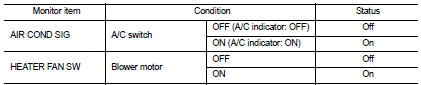
Is the inspection result normal? YES >> Replace IPDM E/R. Refer to PCS-34, "Removal and Installation" (with Intelligent Key) or PCS-63, "Removal and Installation" (without Intelligent Key).
NO >> Replace BCM. Refer to BCS-93, "Removal and Installation" (with Intelligent Key) or BCS-161, "Removal and Installation" (without Intelligent Key).
 Insufficient heating
Description
Symptom
• Insufficient heating
• No warm air comes out. (Air flow volume is normal.)
Diagnosis Procedure
NOTE:
Perform self-diagnoses with CONSULT-III before performing symptom d ...

Other materials:
Diagnosis system (BCM) (with intelligent key system)
Description
Air conditioning system performs self-diagnosis, operation check, function
diagnosis, and various settings
using diagnosis function of each control unit.
Common item : consult-III Function (BCM - COMMON ITEM)
APPLICATION ITEM
CONSULT-III performs the following functions via CAN ...
P0139 HO2S2
DTC Logic
DTC DETECTION LOGIC
The heated oxygen sensor 2 has a much longer switching time
between rich and lean than the air fuel ratio (A/F) sensor 1. The oxygen
storage capacity of the three way catalyst 1 causes the longer
switching time. To judge the malfunctions of heated oxygen sensor
2, ...
TCM branch line circuit
Diagnosis Procedure
1.CHECK CONNECTOR
1. Turn the ignition switch OFF.
2. Disconnect the battery cable from the negative terminal.
3. Check the following terminals and connectors for damage, bend and loose
connection (unit side and connector
side).
- TCM
- Harness connecotor F1
- Harness ...
