
Nissan Juke Service and Repair Manual : Component parts
Component Parts Location
LHD MODELS
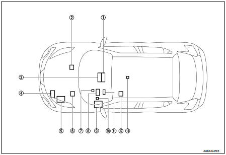
1. Multi display unit
2. ABS actuator and electric unit (control
unit)
3. A/C auto amp. (With auto air conditioning)
PTC heater control unit (Diesel engine
with manual air conditioning)
4. ECM (Gasoline engine models)
5. IPDM E/R
6. TCM (Gasoline engine models)
ECM (Diesel engine models)
7. EPS control unit
8. Combination meter
9. BCM
10. Data link connector
11. Steering angle sensor
12. 4WD control module
13. Air bag diagnosis sensor unit
RHD MODELS
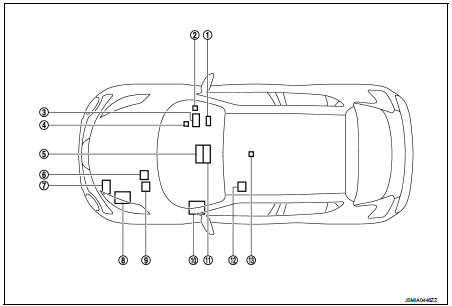
1. Steering angle sensor
2. Data link connector
3. Combination meter
4. EPS control unit
5. A/C auto amp. (With auto air conditioning)
PTC heater control unit (Diesel engine
with manual air conditioning)
6. ABS actuator and electric unit (control
unit)
7. ECM (Gasoline engine models)
8. IPDM E/R
9. TCM (Gasoline engine models)
ECM (Diesel engine models)
10. BCM
11. Multi display unit
12. 4WD control module
13. Air bag diagnosis sensor unit

 System
Can communication system
CAN COMMUNICATION SYSTEM : System Diagram
CAN COMMUNICATION SYSTEM : System Description
Description
• CAN (Controller Area Network) is a serial communication line for ...
Other materials:
NISSAN Intelligent Key Operation
This hands-free proximity system allows you to completely secure or access your vehicle cabin without ever needing to physically retrieve the Intelligent Key transmitter from your pocket, briefcase, or handbag.
As long as you are personally carrying the registere ...
Brake fluid
For comprehensive technical specifications and details regarding recommended fluids, lubricants, and system capacities for your Nissan Leaf, please refer to the "Recommended fluids/lubricants and capacities" section of your manual.
WARNING
Always utilize fresh, high-quality brake ...
P0603 ECM
Description
ECM has the memory function of the DTC memory, the air-fuel ratio
feedback compensation value memory, the Idle Air Volume Learning
value memory, etc. even when the ignition switch is turned OFF.
DTC Logic
DTC DETECTION LOGIC
*: This self-diagnosis is not for ECM power supply ci ...
