Nissan Juke Service and Repair Manual : Camshaft valve clearance
Inspection and Adjustment
INSPECTION
Perform inspection as follows after removal, installation or replacement of camshaft or valve-related parts, or if there is unusual engine conditions regarding valve clearance.
1. Remove rocker cover. Refer to EM-178, "Removal and Installation".
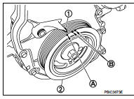
2. Measure the valve clearance with the following procedure: a. Set No. 1 cylinder at TDC of its compression stroke.
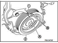
ŌĆó Rotate crankshaft pulley (2) clockwise and align TDC mark (no paint) (A) to timing indicator (1) on front cover.
B : White paint mark (Not use for service)
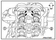
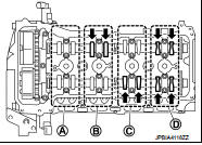
ŌĆó At the same time, check that both intake and exhaust cam
noses of No. 1 cylinder face inside (
) as shown in the figure.
1 : Camshaft (INT)
2 : Camshaft (EXH)
 : Engine front
ŌĆó If they do not face inside, rotate crankshaft pulley once more (360 degrees) and align as shown in the figure.
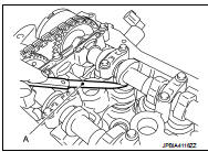
b. Use a feeler gauge (A), measure the clearance between valve lifter and camshaft.
Valve clearance : Refer to EM-251, "Camshaft".
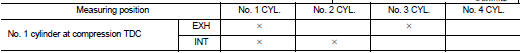
ŌĆó By referring to the figure, measure the valve clearances at
locations marked ŌĆ£×ŌĆØ as shown in the table below [locations
indicated with black arrow (![the figure] with a feeler](images/books/335/4/index.43.gif) ) in
) in
the figure] with a feeler
gauge.
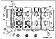
c. Set No. 4 cylinder at TDC of its compression stroke.
ŌĆó Rotate crankshaft pulley (2) one revolution (360 degrees) and align TDC mark (no paint) (A) to timing indicator (1) on front cover.
B : White paint mark (Not use for service)
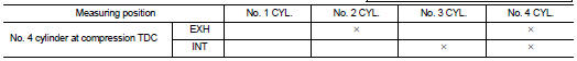
ŌĆó By referring to the figure, measure the valve clearance at locations
marked ŌĆ£×ŌĆØ as shown in the table below [locations indicated
with black arrow ( ) in the figure]
with a feeler gauge.
3. If out of standard, perform adjustment. Refer to ŌĆ£ADJUSTMENTŌĆØ.
ADJUSTMENT
ŌĆó Perform adjustment depending on selected head thickness of valve lifter.
1. Remove camshaft. Refer to EM-191, "Exploded View".
2. Remove valve lifters at the locations that are out of the standard.
3. Measure the center thickness of the removed valve lifters with a micrometer (A).
4. Use the equation below to calculate valve lifter thickness for replacement.
Valve lifter thickness calculation: t = t1 + (C1 ŌĆō C2) t = Valve lifter thickness to be replaced t1 = Removed valve lifter thickness C1 = Measured valve clearance C2 = Standard valve clearance: Intake : 0.30 mm (0.012 in) Exhaust : 0.33 mm (0.013 in)
ŌĆó Thickness of new valve lifter (B) can be identified by stamp mark (A) on the reverse side (inside the cylinder).
ŌĆó Stamp mark ŌĆ£302ŌĆØ indicates 3.02 mm (0.1189 in) in thickness.
NOTE
:
Available thickness of valve lifter: 26 sizes range 3.00 to 3.50 mm (0.1181 to
0.1378 in) in steps of 0.02
mm (0.0008 in) (when manufactured at factory). Refer to EM-251, "Camshaft".
5. Install the selected valve lifter.
6. Install camshaft. Refer to EM-191, "Exploded View".
7. Install timing chain and related parts. Refer to EM-181, "Exploded View".
8. Manually rotate crankshaft pulley a few rotations.
9. Check that the valve clearances is within the standard. Refer to ŌĆ£INSPECTIONŌĆØ.
10. Install remaining parts in the reverse order of removal.
11. Warm up the engine, and check for unusual noise and vibration.
 Basic inspection
...
 Compression pressure
Inspection
1. Warm up engine thoroughly. Then, stop it.
2. Release fuel pressure. Refer to EC-551, "Work Procedure".
3. Remove ignition coil and spark plug from each cylinder. Refer to EM ...
Other materials:
Component parts
Component Parts Location
1. Remote keyless entry receiver
Refer to DLK-21,
"Component Parts Location" (With
super lock) or DLK-198,
"Component Parts Location" (Without
super lock).
2. Combination meter
Refer to MWI-4, "METER SYSTEM :
Component Parts Location" ...
Back door opener system
System Diagram
System Descr
BACK DOOR OPENER OPERATION
When back door opener switch is pressed, BCM operates back door opener
actuator.
NOTE:
Back door opener actuator is not for locking the back door. The function is only
to open the back door.
OPERATION CONDITION
If the following ...
P0725 engine speed
Description
The engine speed signal is transmitted from ECM to TCM by CAN communication
line.
DTC Logic
DTC DETECTION LOGI
DTC CONFIRMATION PROCEDURE
CAUTION:
Always drive vehicle at a safe speed.
NOTE:
If ŌĆ£DTC CONFIRMATION PROCEDUREŌĆØ has been previously performed, always turn
igni ...
