Nissan Juke Service and Repair Manual : C1121, C1123, C1125, C1127 ABS out valve system
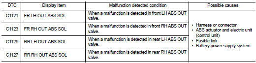
DTC Logic
DTC DETECTION LOGIC
DTC CONFIRMATION PROCEDURE
1.PRECONDITIONING
If ÔÇťDTC CONFIRMATION PROCEDUREÔÇŁ has been previously conducted, always turn ignition switch OFF and wait at least 10 seconds before conducting the next test.
>> GO TO 2.
2.CHECK DTC DETECTION
 With CONSULT-III
1. Turn the ignition switch OFF to ON.
2. Perform self-diagnosis for ÔÇťABSÔÇŁ.
Is DTC ÔÇťC1121ÔÇŁ, ÔÇťC1123ÔÇŁ, ÔÇťC1125ÔÇŁ or ÔÇťC1127ÔÇŁ detected? YES >> Proceed to BRC-58, "Diagnosis Procedure".
NO >> INSPECTION END
Diagnosis Procedure
1.CHECK CONNECTOR
1. Turn the ignition switch OFF.
2. Check ABS actuator and electric unit (control unit) harness connector for disconnection or looseness.
Is the inspection result normal? YES >> GO TO 3.
NO >> Repair or replace error-detected parts, securely lock the connector, and GO TO 2.
2.PERFORM SELF-DIAGNOSIS
Perform self-diagnosis for ÔÇťABSÔÇŁ again.
Is DTC ÔÇťC1121ÔÇŁ, ÔÇťC1123ÔÇŁ, ÔÇťC1125ÔÇŁ or ÔÇťC1127ÔÇŁ detected? YES >> GO TO 3.
NO >> INSPECTION END
3.CHECK ABS OUT VALVE POWER SUPPLY
1. Turn the ignition switch OFF.
2. Disconnect ABS actuator and electric unit (control unit) harness connector.
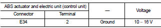
3. Check voltage between ABS actuator and electric unit (control unit) harness connector and ground.
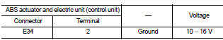
4. Turn the ignition switch ON.
CAUTION:
Never start engine.
5. Check voltage between ABS actuator and electric unit (control unit) harness connector and ground.
Is the inspection result normal? YES >> GO TO 5.
NO >> GO TO 4.
4.CHECK ABS OUT VALVE POWER SUPPLY CIRCUIT
1. Turn the ignition switch OFF.
2. Check 40 A fusible link (F).
3. Check continuity and short circuit between ABS actuator and electric unit (control unit) harness connector terminal (2) and 40 A fusible link (F).
Is the inspection result normal? YES >> Perform trouble diagnosis for battery power supply. Refer to PG-10, "Wiring Diagram - BATTERY POWER SUPPLY -".
NO >> Repair or replace error-detected parts.
5.CHECK ABS OUT VALVE GROUND CIRCUIT
1. Turn the ignition switch OFF.
2. Check continuity between ABS actuator and electric unit (control unit) harness connector and the ground.
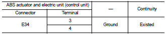
Is the inspection result normal? YES >> GO TO 6.
NO >> Repair or replace error-detected parts.
6.CHECK TERMINAL
Check ABS actuator and electric unit (control unit) pin terminals for damage or loose connection with harness connector.
Is the inspection result normal? YES >> Replace ABS actuator and electric unit (control unit). Refer to BRC-90, "Removal and Installation".
NO >> Repair or replace error-detected parts.
 C1120, C1122, C1124, C1126 ABS in valve system
DTC Logic
DTC DETECTION LOGIC
DTC CONFIRMATION PROCEDURE
1.PRECONDITIONING
If ÔÇťDTC CONFIRMATION PROCEDUREÔÇŁ has been previously conducted, always turn
ignition switch OFF and
wait at least ...
 C1140 actuator relay system
DTC Logic
DTC DETECTION LOGIC
DTC CONFIRMATION PROCEDURE
1.PRECONDITIONING
If ÔÇťDTC CONFIRMATION PROCEDUREÔÇŁ has been previously conducted, always turn
ignition switch OFF and
wait at least ...
Other materials:
System malfunction
If the AEB with Pedestrian Detection system encounters a technical error or internal fault, it will automatically deactivate to ensure vehicle safety. When this occurs, you will hear an audible chime, the AEB with Pedestrian Detection system warning light will illuminate in ora ...
Rear door
Exploded View
1. Rear door panel
2. TORX bolt
3. Door striker
4. Door check link
5. Door hinge (lower)
6. Door hinge (upper)
: Do not reuse
: N┬Ěm (kg-m, in-lb)
: N┬Ěm (kg-m, ft-lb)
: Body grease
Door assembly
DOOR ASSEMBLY : Removal and Installation
CAUTION:
ÔÇó Perform work wit ...
B263D, B263E, B263F intake door motor
DTC Logic
DTC DETECTION LOGIC
DTC CONFIRMATION PROCEDURE
1.PERFORM DTC CONFIRMATION PROCEDURE
With CONSULT-III
1. Turn ignition switch ON.
2. Select ÔÇťSelf Diagnostic ResultÔÇŁ mode of ÔÇťHVACÔÇŁ using CONSULT-III.
3. Check DTC.
Is DTC detected?
YES >> Refer to HAC-159, "Dia ...
