Nissan Juke Service and Repair Manual : BCM, ECM, IPDM E/R
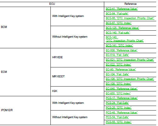
List of ECU Reference
 PTC heater control unit
Reference Value
CONSULT-III DATA MONITOR REFERENCE VALUES
TERMINAL LAYOUT
PHYSICAL VALUES
DTC Index
...
 Wiring diagram
MANUAL AIR CONDITIONING SYSTEM
Wiring Diagram
For connector terminal arrangements, harness layouts, and alphabets in a
(option abbreviation; if not
described in wiring diagram), refer to GI-12, &q ...
Other materials:
P0107, P0108 atmospheric pressure
sensor
DTC Logic
DTC DETECTION LOGIC
DTC CONFIRMATION PROCEDURE
1.PRECONDITIONING
If DTC Confirmation Procedure has been previously conducted, always perform
the following procedure
before conducting the next test.
1. Turn ignition switch OFF and wait at least 10 seconds.
2. Turn ignition swi ...
System
Body control system
BODY CONTROL SYSTEM : System Description
OUTLINE
• BCM (Body Control Module) controls the various electrical components. It
inputs the information required to
the control from CAN communication and the signal received from each switch and
sensor.
• BCM has combinatio ...
Rear seat (2WD)
Exploded View
1. Headrest
2. Headrest holder (locked)
3. Headrest holder (free)
4. Seatback trim RH
5. Seatback pad RH
6. Seat lock cover RH
7. Seatback lock knob
8. Seatback lock knob finisher
9. Seatback lock assembly RH
10. Striker RH
11. Lock washer
12. Side hinge
13. Bush ...
