Nissan Juke Service and Repair Manual : B1132 side air bag module RH
DTC Logic
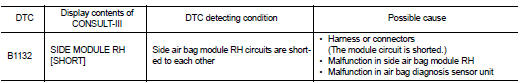
DTC DETECTION LOGIC
DTC CONFIRMATION PROCEDURE
1.CHECK SELF-DIAG RESULT
 With CONSULT-III
1. Turn ignition switch ON.
2. Perform ŌĆ£Self Diagnostic ResultŌĆØ mode of ŌĆ£AIR BAGŌĆØ using CONSULT-III.
 Without CONSULT-III
1. Turn ignition switch ON.
2. Check the air bag warning lamp status. Refer to SRC-12, "On Board Diagnosis Function".
NOTE
:
SRS does not enter the diagnosis mode if no malfunction is detected in the user
mode.
Is malfunctioning part detected? YES >> Refer to SRC-100, "Diagnosis Procedure".
NO >> INSPECTION END
Diagnosis Procedure
WARNING:
ŌĆó Before servicing, turn ignition switch OFF, disconnect battery negative
terminal, and wait at least 3
minutes or more. (To discharge backup capacitor.)
ŌĆó Never use unspecified tester or other measuring device.
1.CHECK HARNESS CONNECTOR
Check the harness connector.
Is the inspection result normal? YES >> GO TO 2.
NO >> Replace harness connector.
2.CHECK WIRING HARNESS
Check the wiring harness externals.
Is the inspection result normal? YES >> GO TO 3.
NO >> Replace wiring harness.
3.REPLACE AIR BAG DIAGNOSIS SENSOR UNIT
1. Replace air bag diagnosis sensor unit. Refer to SR-30, "Removal and Installation".
2. Perform DTC confirmation procedure. Refer to SRC-100, "DTC Logic".
Is DTC detected? YES >> GO TO 4.
NO >> INSPECTION END
4.REPLACE SIDE AIR BAG MODULE
1. Replace side air bag module RH. Refer to SR-22, "Removal and Installation".
2. Perform DTC confirmation procedure. Refer to SRC-100, "DTC Logic".
Is DTC detected?
YES >> GO TO 1.
NO >> INSPECTION END
 B1131 side air bag module RH
DTC Logic
DTC DETECTION LOGIC
DTC CONFIRMATION PROCEDURE
1.CHECK SELF-DIAG RESULT
With CONSULT-III
1. Turn ignition switch ON.
2. Perform ŌĆ£Self Diagnostic ResultŌĆØ mode of ŌĆ£AIR BAGŌĆØ usi ...
 B1134 side air bag module LH
DTC Logic
DTC DETECTION LOGIC
DTC CONFIRMATION PROCEDURE
1.CHECK SELF-DIAG RESULT
With CONSULT-III
1. Turn ignition switch ON.
2. Perform ŌĆ£Self Diagnostic ResultŌĆØ mode of ŌĆ£AIR BAGŌĆØ usi ...
Other materials:
Door cable
Exploded View
LEFT SIDE
1. Heater unit assembly
2. Intake door lever
3. Intake door link
4. Intake door cable
5. Air mix door cable
6. Air mix door link
7. Air mix door rod
8. Lower air mix door lever
9. Upper air mix door lever
10. Max. cool door
A. To A/C control
RIGHT SIDE
...
Wiring diagram
Engine control system
For connector terminal arrangements, harness layouts, and alphabets in a
(option abbreviation; if not
described in wiring diagram), refer to GI-12, "Connector Information/Explanation
of Option Abbreviation".
...
Engine control system symptoms
Symptom Table
SYSTEM ŌĆö BASIC ENGINE CONTROL SYSTEM
1 - 6: The numbers refer to the order of inspection.
(continued on next table)
SYSTEM ŌĆö ENGINE MECHANICAL & OTHER
1 - 6: The numbers refer to the order of inspection ...
