Nissan Juke Service and Repair Manual : Door cable
Exploded View
LEFT SIDE
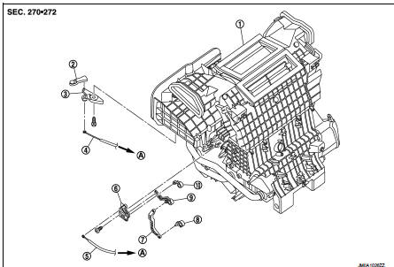
1. Heater unit assembly
2. Intake door lever
3. Intake door link
4. Intake door cable
5. Air mix door cable
6. Air mix door link
7. Air mix door rod
8. Lower air mix door lever
9. Upper air mix door lever
10. Max. cool door
A. To A/C control
RIGHT SIDE
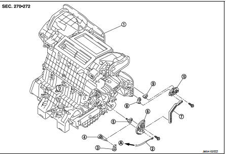
1. Heater unit assembly
2. Mode door cable
3. Foot door lever
4. Foot door link
5. Side ventilator door lever
6. Mode door main link
7. Mode door main link adapter rod
8. Center ventilator door lever
9. Defroster door lever
10. Mode door main link adapter
A. To A/C control
Intake door cable : Removal and Installation
REMOVAL
1. Disconnect intake door cable from A/C control. Refer to HAC-308, "Exploded View".
2. Remove instrument lower panel LH. Refer to IP-13, "Removal and Installation".
(LHD models)
3. Remove glove box assembly. Refer to IP-13, "Removal and Installation". (RHD
models)
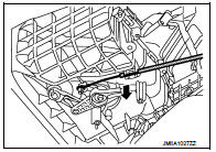
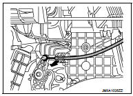
4. Disconnect intake door cable from heater unit assembly as
shown by the arrow in the figure, and then remove intake door
cable.
INSTALLATION
Install in the reverse order of removal.
Mode door cable : Removal and Installation
REMOVAL
1. Disconnect mode door cable from A/C control. Refer to HAC-308, "Exploded View".
2. Remove glove box assembly. Refer to IP-13, "Removal and Installation". (LHD
models)
3. Remove instrument panel RH. Refer to IP-13, "Removal and Installation". (RHD
models)
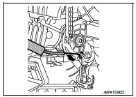
4. Disconnect mode door cable from heater unit assembly as
shown by the arrow in the figure, and then remove mode door
cable.
INSTALLATION
Install in the reverse order of removal.
Air mix door cable : Removal and Installation
REMOVAL
1. Disconnect air mix door cable from A/C control. Refer to HAC-308, "Exploded View".
2. Remove instrument panel LH. Refer to IP-13, "Removal and Installation". (LHD
models)
3. Remove glove box assembly. Refer to IP-13, "Removal and Installation". (RHD
models)
4. Disconnect air mix door cable from heater unit assembly as
shown by the arrow in the figure, and then remove air mix door
cable.
INSTALLATION
Install in the reverse order of removal.
 Blower fan resistor
Exploded View
1. Heater unit assembly
2. Fan control amp.*1
3. Blower fan resistor*2
4. Blower motor
5. Blower motor cover
• *1: Automatic air conditioner
• *2: Manual air conditioner ...
 Interior
...
Other materials:
Transmission range switch
Exploded View
1. Transmission range switch
2. Transaxle assem
Removal and Installation
REMOVAL
1. Remove battery. Refer to PG-124, "Removal and Installation".
2. Remove transmission range switch connector.
3. Remove control cable. Refer to TM-273, "Removal and Installation&q ...
B210C starter control relay
DTC Logic
DTC DETECTION LOGIC
NOTE:
• If DTC B210C is displayed with DTC U1000, first perform the trouble diagnosis
for DTC U1000. Refer to
PCS-30, "DTC Logic".
• When IPDM E/R power supply voltage is low (Approx. 7 - 8 V for about 1
second), the DTC B210C may be
detected.
...
P2765 clutch B speed sensor
DTC Logic
DTC DETECTION LOGIC
DTC CONFIRMATION PROCEDURE
CAUTION:
Be careful of the driving speed.
1.PREPARATION BEFORE WORK
If another "DTC CONFIRMATION PROCEDURE" occurs just before, turn ignition
switch OFF and wait for at
least 10 seconds, then perform the next test.
> ...
