Nissan Juke Service and Repair Manual : Additional service when removing battery negative terminal
Description
ÔÇó The NAVI control unit is equipped with the anti-theft system.
ÔÇó The NAVI control unit operates after authenticating a fixed four-digit anti-theft code.
ÔÇó After removing the battery of the NAVI control unit, the authentication of the anti-theft code is required.
Work Procedure
1.POWER SWITCH ON
1. Turn ignition switch ON.
2. Turn ON the power switch of the NAVI control unit. (ÔÇťCODE INÔÇŁ is indicated on the display.) >> GO TO 2.
2.ANTI-THEFT CODE INPUT (FOUR DIGIT CODE)
1. Touch the button shown on the display to enter code numbers.
2. Touch OK button.
Is ÔÇťCODE OKÔÇŁ displayed? YES >> END NO >> GO TO 3.
3.RETRY ANTI-THEFT CODE INPUT (FOUR DIGIT CODE)
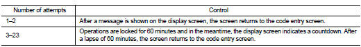
1. If the anti-theft code cannot be authenticated, the NAVI control unit performs control as follows:
CAUTION:
ÔÇó 24 or more: Operations are locked and a message is shown on the display. Code
numbers cannot
be input.
ÔÇó The number of failed attempts is not reset and accumulated after any authentication
.
2. Wait until ÔÇťCODE INÔÇŁ is displayed.
>> GO TO 2.
 Diagnosis and repair work flow
Work Flow
OVERALL SEQUENCE
Reference 1┬Ě┬Ě┬Ě Refer to AV-77, "Symptom Table".
DETAILED FLOW
1.CHECK SYMPTOM
Check the malfunction symptoms by performing the following items.
ÔÇó ...

Other materials:
Sun visors
1. To effectively block blinding sunlight or glare originating from directly ahead, simply swing down 1 the primary sun visor assembly toward the windshield.
2. To block harsh rays penetrating from the side glass, unclip the main sun visor from its central plasti ...
Seats, seat belts, and the Supplemental Restraint System (SRS)
Rear head restraints: Adjustable for optimal support and whiplash protection.
Child restraint anchor points: Secure attachment points specifically designed for top tether straps to keep child seats stable.
Roof-mounted curtain side-impact and rollove ...
P0840 transmission fluid pressure SEN/SW A
DTC Logic
DTC DETECTION LOGIC
DTC CONFIRMATION PROCEDURE
NOTE:
If ÔÇťDTC CONFIRMATION PROCEDUREÔÇŁ has been previously performed, always turn
ignition switch
OFF and wait at least 10 seconds before performing the next test.
After the repair, perform the following procedure to confirm the ...
