Nissan Juke Service and Repair Manual : Diagnosis and repair workflow
Work Flow
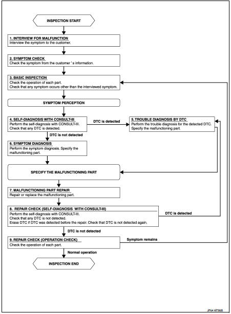
OVERALL SEQUENCE
DETAILED FLOW
1.INTERVIEW FOR MALFUNCTION
Interview the symptom to the customer.
>> GO TO 2.
2.SYMPTOM CHECK
Check the symptom from the customer's information.
>> GO TO 3.
3.BASIC INSPECTION Check the operation of each part. Check that any symptom occurs other than the interviewed symptom.
>> GO TO 4.
4.SELF-DIAGNOSIS WITH CONSULT-III
Perform the self-diagnosis with CONSULT-III. Check that any DTC is detected.
Is any DTC detected? YES >> GO TO 5.
NO >> GO TO 6.
5.TROUBLE DIAGNOSIS BY DTC
Perform the trouble diagnosis for the detected DTC. Specify the malfunctioning part.
>> GO TO 6.
6.SYMPTOM DIAGNOSIS
Perform the symptom diagnosis. Specify the malfunctioning part.
>> GO TO 7.
7.MALFUNCTION PART REPAIR
Repair or replace the malfunctioning part.
>> GO TO 8.
8.REPAIR CHECK (SELF-DIAGNOSIS WITH CONSULT-III)
Perform the self-diagnoses with CONSULT-III. Check that any DTC is not detected. Erase DTC if DTC is detected before the repair. Check that DTC is not detected again.
Is any or malfunction result or DTC detected? YES >> If DTC is detected, GO TO 5.
NO >> GO TO 9.
9.REPAIR CHECK (OPERATION CHECK)
Check the operation of each part.
Does it operate normally? YES >> INSPECTION END
NO >> GO TO 3.
 Basic inspection
...
 Operation inspection
Work Procedure
The purpose of the operational check is to check that the individual system
operates normally.
Check condition : Engine running at normal operating temperature.
1.CHECK BLOWER MOTO ...
Other materials:
Transaxle assembly
Exploded View
CASE AND HOUSING
1. Filler plug
2. Gasket
3. Transaxle case
4. Bushing
5. Snap ring
6. Oil channel
7. Oil gutter
8. Position switch
9. Bracket
10. Differential side oil seal
11. Magnet
12. Drain plug
13. Input shaft oil seal
14. Clutch housing
15. 2 way conn ...
Cylinder head
Exploded View
REMOVAL
1. Cylinder head assembly
2. Cylinder head bolt
3. Cylinder head gasket
A. Tightening must be done following
the installation procedure.
Refer to EM-91
: N·m (kg-m, ft-lb)
: Always replace after every
disassembly.
: Should be lubricated with oil.
DISASSEMBLY ...
Trouble diagnosis - specification valuE
Description
The specification (SP) value indicates the tolerance of the value that is
displayed in “SPEC” of “DATA MONITOR”
mode of CONSULT-III during normal operation of the Engine Control System. When
the value in “SPEC”
of “DATA MONITOR” mode is within the SP value, the Eng ...
