Nissan Juke Service and Repair Manual : Structure and operation
Sectional View
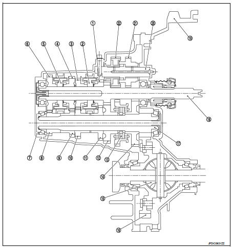
1. 3rd input gear
2. 3rd-4th synchronizer hub assembly
3. 4th input gear
4. 5th input gear
5. 5th-6th synchronizer hub assembly
6. 6th input gear
7. Transaxle case
8. 6th main gear
9. 5th main gear
10. 4th main gear
11. 3rd main gear
12. 2nd main gear
13. 1st-2nd synchronizer hub assembly
14. 1st main gear
15. Differential
16. Final gear
17. Mainshaft
18. Input shaft
19. Clutch housing
20. Reverse idler shaft
21. Reverse input gear
22. Reverse output gear
System Description
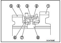
TRIPLE-CONE SYNCHRONIZER
Triple-cone synchronizers are adopted for the 1st and the 2nd gears to reduce operating force of the shifter lever.
1 : 1st main gear
2 : 1st-2nd coupling sleeve
3 : Insert key
4 : Outer baulk ring
5 : 2nd main gear
6 : Synchronizer cone
7 : Inner baulk ring
8 : 1st-2nd synchronizer hub
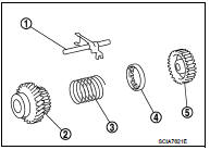
REVERSE GEAR NOISE PREVENTION FUNCTION (SYNCHRONIZING METHOD)
Reverse gear assembly consists of reverse input gear, return spring, reverse baulk ring, and reverse output gear. When the shifter lever is shifted to the reverse position, the construction allows smooth shift operation by stopping the reverse idler shaft rotation by frictional force of synchronizer.
1 : Reverse fork rod
2 : Reverse output gear
3 : Return spring
4 : Reverse baulk ring
5 : Reverse input gear
 Component parts
Component Parts Location
POSITION SWITCH
1 : Position switch
...
 DTC/Circuit diagnosis
POSITION SWITCH ...
Other materials:
Precaution
Precautions for Trouble Diagnosis
CAUTION:
• Never apply 7.0 V or more to the measurement terminal.
• Use a tester with open terminal voltage of 7.0 V or less.
• Turn the ignition switch OFF and disconnect the battery cable from the
negative terminal when
checking the harness.
Precautions fo ...
S mode switch
Component Function Check
1.CHECK S MODE INDICATOR FUNCTION
Check S mode indicator turns ON for approx. 2 seconds when ignition switch
turns ON.
Is the inspection results normal?
YES >> GO TO 2.
NO >> Go to TM-469, "Diagnosis Procedure".
2.CHECK S MODE SWITCH FUNCT ...
A/C switch
Component Function Check
1.CHECK A/C ON SIGNAL
With CONSULT-III
1. Turn ignition switch ON.
2. Select “AIR CONDITIONER” of “BCM” using CONSULT-III.
3. Select “AIR COND SW” in “DATA MONITOR” mode, and check status under the
following condition.
Is the inspection result normal?
YES >> ...
