Nissan Juke Service and Repair Manual : A/C switch
Component Function Check
1.CHECK A/C ON SIGNAL
 With CONSULT-III
1. Turn ignition switch ON.
2. Select “AIR CONDITIONER” of “BCM” using CONSULT-III.
3. Select “AIR COND SW” in “DATA MONITOR” mode, and check status under the following condition.
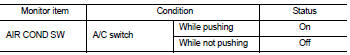
Is the inspection result normal? YES >> INSPECTION END
NO >> Refer to HAC-220, "Diagnosis Procedure".
Diagnosis Procedure
1.CHECK A/C SWITCH POWER SUPPLY
1. Turn ignition switch OFF.
2. Disconnect A/C control connector.
3. Turn ignition switch ON.
4. Check output waveform between A/C control harness connector and ground with using oscilloscope.
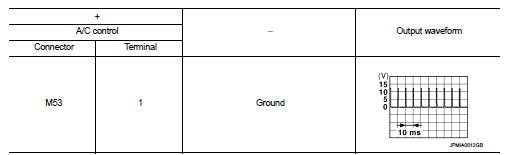
Is the inspection result normal? YES >> GO TO 2.
NO >> GO TO 3.
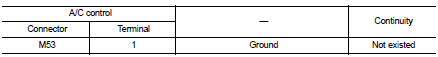
2.CHECK A/C SWITCH GROUND CIRCUIT FOR OPEN
1. Turn ignition switch OFF.
2. Disconnect BCM connector.
3. Check continuity between A/C control harness connector and ground.
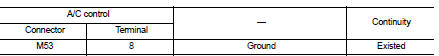
Is the inspection result normal? YES >> Replace A/C control. Refer to HAC-239, "Removal and Installation".
NO >> Repair harness or connector.
3.CHECK A/C SWITCH POWER SUPPLY CIRCUIT FOR OPEN
1. Turn ignition switch OFF.
2. Disconnect BCM connector.
3. Check continuity between A/C control harness connector and BCM harness connector.
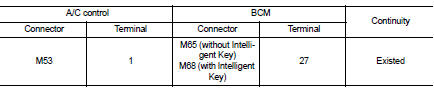
Is the inspection result normal? YES >> GO TO 4.
NO >> Repair harness or connector.
4.CHECK A/C SWITCH POWER SUPPLY CIRCUIT FOR SHORT
Check continuity between A/C control harness connector and ground.
Is the inspection result normal? YES >> Replace BCM. Refer to BCS-93, "Removal and Installation" (with Intelligent Key) or BCS-161, "Removal and Installation" (without Intelligent Key).
NO >> Repair harness or connector.

 Blower fan on signal
Component Function Check
1.CHECK BLOWER FAN ON SIGNAL
With CONSULT-III
1. Turn ignition switch ON.
2. Select “AIR CONDITIONER” of “BCM” using CONSULT-III.
3. Select “FAN ON SIG” in “DATA MONITOR” ...
Other materials:
Fuel tank
2WD : Exploded View
1. Fuel filler cap
2. Grommet
3. Fuel filler tube
4. EVAP canister hose
5. Fuel tank mounting band (RH)
6. Fuel tank mounting band (LH)
7. Fuel tank
8. Clamp
9. Fuel filler hose
10. Vent hose
Vehicle front
: N?·m (kg-m, ft-lb)
2WD : Removal and Installation
...
P0102, P0103 MAF SENSOR
DTC Logic
DTC DETECTION LOGIC
DTC CONFIRMATION PROCEDURE
1.PRECONDITIONING
If DTC Confirmation Procedure has been previously conducted, always turn
ignition switch OFF and wait at
least 10 seconds before conducting the next test.
Which DTC is detected?
P0102 >> GO TO 2.
P0103 & ...
Door mirror defogger does not operate
Both sides
BOTH SIDES : Description
Both door mirror defoggers do not operate
BOTH SIDES : Diagnosis Procedure
1.CHECK REAR WINDOW DEFOGGER
Check rear window defogger.
Refer to DEF-31, "Component Function Check".
Is the inspection result normal?
YES >> GO TO 2.
NO > ...
