Nissan Juke Service and Repair Manual : S mode switch
Component Function Check
1.CHECK S MODE INDICATOR FUNCTION
Check S mode indicator turns ON for approx. 2 seconds when ignition switch turns ON.
Is the inspection results normal? YES >> GO TO 2.
NO >> Go to TM-469, "Diagnosis Procedure".
2.CHECK S MODE SWITCH FUNCTION
1. Shift the selector lever to “D” position.
2. Check that S mode indicator turns ON/OFF when S mode switch is operated.
Is the inspection results normal? YES >> INSPECTION END NO >> Go to TM-466, "Diagnosis Procedure".
Diagnosis Procedure
1.CHECK S MODE SWITCH CIRCUIT
1. Turn ignition switch OFF.
2. Disconnect CVT shift selector connector.
3. Turn ignition switch ON.
4. Check the voltage between CVT shift selector harness connector terminals
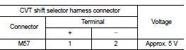
Is the inspection result normal? YES >> GO TO 2.
NO >> GO TO 4.
2.CHECK S MODE SWITCH
Check S mode switch. Refer to TM-467, "Component Inspection (S Mode Switch)".
Is the inspection result normal? YES >> GO TO 3.
NO >> Repair or replace the malfunctioning parts.
3.CHECK CVT SHIFT SELECTOR HARNESS
Check CVT shift selector harness. Refer to TM-467, "Component Inspection (CVT Shift Selector Harness)".
Is the inspection result normal? YES >> Check intermittent incident. Refer to GI-42, "Intermittent Incident".
NO >> Repair or replace the malfunctioning parts.
4.CHECK GROUND CIRCUIT
Check the continuity between CVT shift selector harness connector terminal and ground.
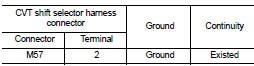
Is the inspection result normal? YES >> GO TO 5.
NO >> Repair or replace the malfunctioning parts.
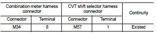
5.CHECK CIRCUIT BETWEEN COMBINATION METER AND CVT SHIFT SELECTOR (PART 1)
1. Turn ignition switch OFF.
2. Disconnect combination meter connector.
3. Check the continuity between combination meter harness connector terminal and CVT shift selector harness connector terminal.
Is the inspection result normal? YES >> GO TO 6.
NO >> Repair or replace the malfunctioning parts.
6.CHECK CIRCUIT BETWEEN COMBINATION METER AND CVT SHIFT SELECTOR (PART 2)
Check the continuity between combination meter harness connector terminal and ground.
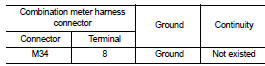
Is the inspection result normal? YES >> GO TO 7.
NO >> Repair or replace the malfunctioning parts.
7.CHECK COMBINATION METER INPUT SIGNAL
1. Connect all of the disconnected connectors.
2. Turn ignition switch ON.
3. Select “Data Monitor” in “METER/M&A”.
4. Select “O/D OFF SW”.
5. Check that “O/D OFF SW” turns ON/OFF when S mode switch is operated. Refer to MWI-28, "Reference Value".
Is the inspection result normal? YES >> Check intermittent incident. Refer to GI-42, "Intermittent Incident".
NO >> Replace combination meter. Refer to MWI-69, "Removal and Installation".
Component Inspection (S Mode Switch)
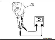
1.CHECK S MODE SWITCH
Check the continuity between wires of selector lever knob (1)
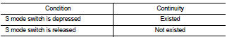
Is the inspection result normal? YES >> INSPECTION END
NO >> Replace the selector lever knob. Refer to TM-482, "Disassembly and Assembly".
Component Inspection (CVT Shift Selector Harness)
1.CHECK CVT SHIFT SELECTOR HARNESS
Check the continuity between harness plate (A) and CVT shift selector harness connector (B).
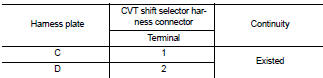
Is the inspection result normal? YES >> INSPECTION END
NO >> Replace CVT shift selector harness. Refer to TM-482, "Disassembly and
Assembly".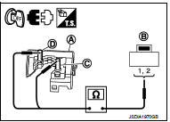
 Main power supply and ground circuit
Diagnosis Procedure
1.CHECK TCM POWER CIRCUIT 1
1. Turn the ignition switch OFF.
2. Disconnect the TCM connector.
3. Check the voltage between the TCM harness connector terminals and ground.
Is ...
 S mode indicator
Component Function Check
1.CHECK S MODE INDICATOR FUNCTION
Check S mode indicator turns ON for approx. 2 seconds when ignition switch
turns ON.
Is the inspection results normal?
YES >> I ...
Other materials:
Hood lock
Exploded View
1. Hood lock control cable assembly
2. Hood lock assembly
: Clip
: N·m (kg-m, ft-lb)
: Body grease
Hood lock
HOOD LOCK : Removal and Installation
REMOVAL
1. Remove front center grille. Refer to EXT-18, "Removal and Installation".
2. Remove crash zone sensor. Refe ...
P183F gear position signal
DTC Logic
DTC DETECTION LOGIC
DTC CONFIRMATION PROCEDURE
1.PRECONDITIONING
If “DTC CONFIRMATION PROCEDURE” has been previously conducted, always turn
ignition switch OFF and
wait at least 10 seconds before conducting the next test.
>> GO TO 2.
2.DTC REPRODUCTION PROCEDURE
With ...
Speed limiter
SPEED LIMITER : Switch Name and Function
SWITCHES AND INDICATORS
NOTE:
Shared with ASCD switch.
1. Speed limiter indicator
2. SET indicator
3. Set speed indicator
4. CANCEL switch
5. RES / + switch
6. SET / − switch
7. Speed limiter MAIN Switch
8. ASCD MAIN switch
A. On the ...
