Nissan Juke Service and Repair Manual : Wiring diagram
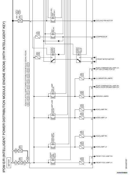
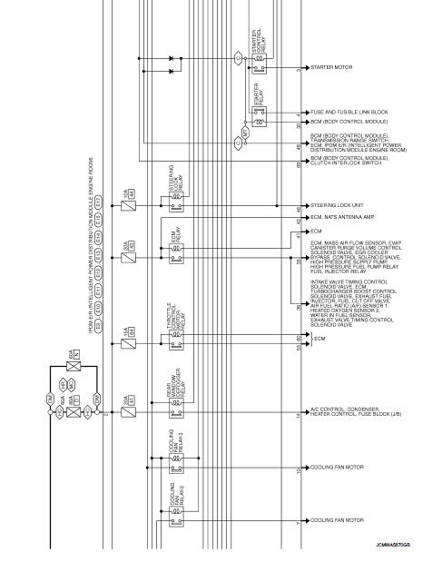
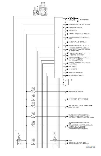
IPDM E/R
Wiring Diagram
For connector terminal arrangements, harness layouts, and alphabets in a
 (option abbreviation; if not
described in wiring diagram), refer to GI-12, "Connector Information/Explanation
of Option Abbreviation".
 ECU diagnosis information
IPDM E/R
Reference Value
VALUES ON THE DIAGNOSIS TOOL
TERMINAL LAYOUT
PHYSICAL VALUES
*1: MR16DDT engine models
*2: Except MR16DDT engine models
*3: CVT models
*4: M/T models ...

Other materials:
System
Manual air conditioning system : System Diagram
Manual air conditioning system : System Description
DESCRIPTION
• Manual air conditioning system is controlled by each function of thermo
control amp., BCM, ECM and IPDM
E/R.
• Fan speed of blower motor is changed by the combination of fan ...
Normal operating condition
Description
FUEL CUT CONTROL (AT NO LOAD AND HIGH ENGINE SPEED)
If the engine speed is above 2,400 rpm under no load (for example, the shift
lever position is neutral and
engine speed is over 2,400 rpm) fuel will be cut off after some time. The exact
time when the fuel is cut off varies
base ...
Back door does not opened
Diagnosis Procedure
1.CHECK BACK DOOR OPENER SWITCH
Check back door opener switch.
Refer to DLK-513, "Component Function Check".
Is the inspection result normal?
YES >> GO TO 2.
NO >> Repair or replace the malfunctioning parts.
2.CHECK BACK DOOR OPENER ACTUATOR
...
