Nissan Juke Service and Repair Manual : ECU diagnosis information
IPDM E/R
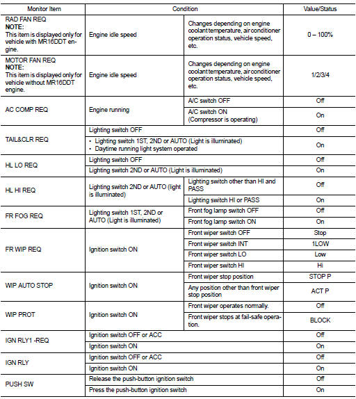
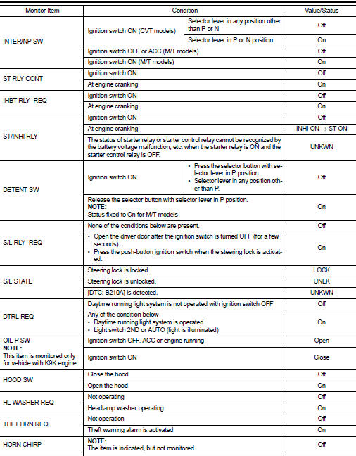
Reference Value
VALUES ON THE DIAGNOSIS TOOL
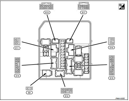
TERMINAL LAYOUT
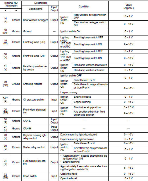
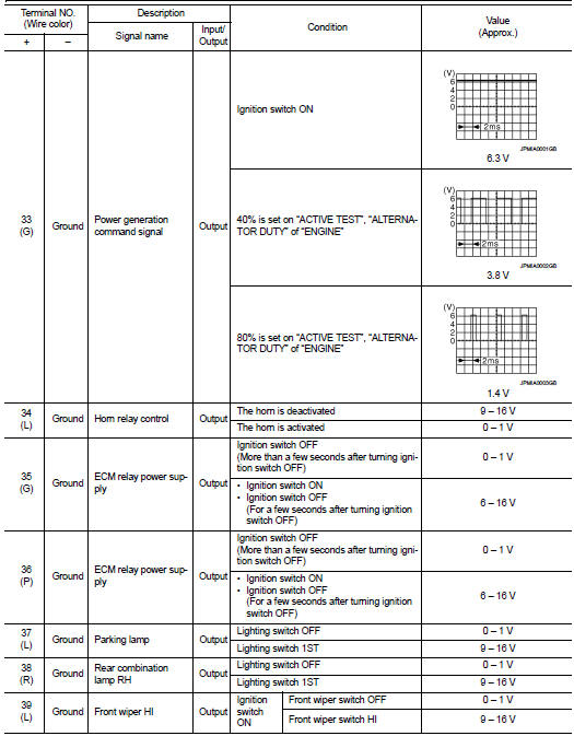
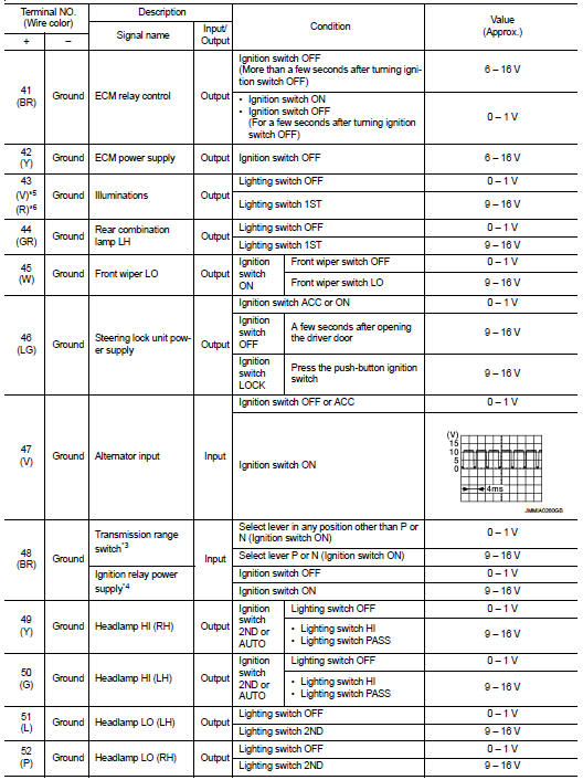
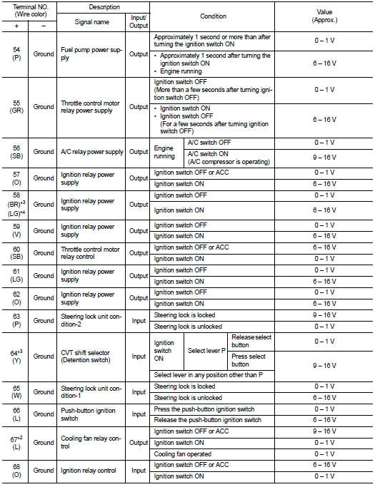
PHYSICAL VALUES
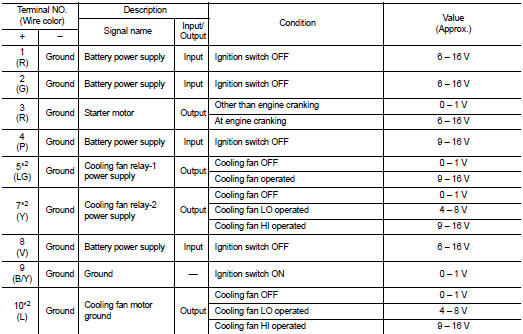
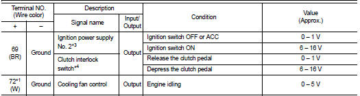
*1: MR16DDT engine models
*2: Except MR16DDT engine models
*3: CVT models
*4: M/T models
*5: With daytime running light system
*6: Without daytime running light system
*7: K9K engine models
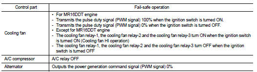
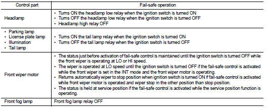
Fail-Safe
CAN COMMUNICATION CONTROL
When CAN communication with ECM and BCM is impossible, IPDM E/R performs fail-safe control. After CAN communication recovers normally, it also returns to normal control.
If No CAN Communication Is Available With ECM
If No CAN Communication Is Available With BCM
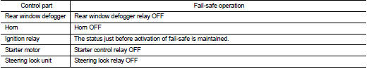
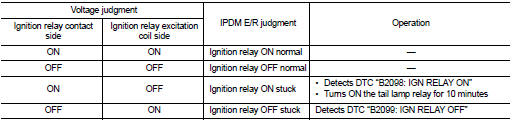
IGNITION RELAY MALFUNCTION DETECTION FUNCTION
ŌĆó IPDM E/R monitors the voltage at the contact circuit and excitation coil circuit of the ignition relay inside it.
ŌĆó IPDM E/R judges the ignition relay error if the voltage differs between the contact circuit and the excitation coil circuit.
ŌĆó If the ignition relay cannot turn OFF due to contact seizure, it activates the tail lamp relay for 10 minutes to alert the user to the ignition relay malfunction when the ignition switch is turned OFF.
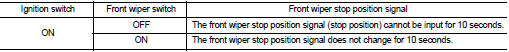
FRONT WIPER PROTECTION FUNCTION
IPDM E/R detects front wiper stop position by a front wiper stop position signal.
When a front wiper stop position signal is in the conditions listed below, IPDM E/R stops power supply to wiper after repeating a front wiper 10 seconds activation and 20 seconds stop.
NOTE
:
This operation status can be confirmed on the IPDM E/R ŌĆ£Data MonitorŌĆØ that
displays ŌĆ£BLOCKŌĆØ for the item
ŌĆ£WIP PROTŌĆØ while the wiper is stopped.
STARTER MOTOR PROTECTION FUNCTION
IPDM E/R turns OFF the starter control relay to protect the starter motor when the starter control relay remains active for 90 seconds.
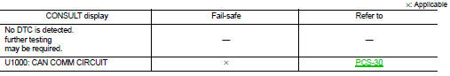
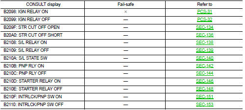
DTC Index
NOTE
:
ŌĆó The details of time display are as follows.
- CRNT: A malfunction is detected now.
- PAST: A malfunction was detected in the past.
ŌĆó IGN counter is displayed on FFD (Freeze Frame Data).
- The number is 0 when is detected now.
- The number increases like 1 → 2 ┬Ę┬Ę┬Ę 38 → 39 after returning to the normal condition whenever IGN OFF → ON.
- The number is fixed to 39 until the self-diagnosis results are erased if it is over 39.
 Diagnosis system (IPDM E/R)
Diagnosis Description
AUTO ACTIVE TEST
Description
In auto active test mode, the IPDM E/R sends a drive signal to the following
systems to check their operation.
ŌĆó Oil pressure warning lamp ...
 Wiring diagram
IPDM E/R
Wiring Diagram
For connector terminal arrangements, harness layouts, and alphabets in a
(option abbreviation; if not
described in wiring diagram), refer to GI-12, "Connector Informa ...
Other materials:
Fuses
Motor compartment
WARNING
Under no circumstances should you touch, disassemble, remove, or replace any high-voltage components, cables, or their associated connectors. High-voltage cables in your Nissan Leaf are identified by their distinctive orange outer i ...
SPEED LIMITER MAIN SWITCH
Component Function Check
1.CHECK SPEED LIMITER MAIN SWITCH FUNCTION
With CONSULT-III
1. Turn ignition switch ON.
2. Select ŌĆ£SL MAIN SWŌĆØ in ŌĆ£DATA MONITORŌĆØ mode of ŌĆ£ENGINEŌĆØ using CONSULT-III.
3. Check ŌĆ£SL MAIN SWŌĆØ indication as per the following condition.
Without CONSULT-III
...
Liquid Gasket
REMOVAL OF LIQUID GASKET
ŌĆó After removing mounting nuts and bolts, separate the mating surface
using the seal cutter [SST: KV10111100] (A) and remove old
liquid gasket sealing.
CAUTION:
Be careful not to damage the mating surfaces.
ŌĆó Tap the seal cutter [SST: KV10111100] to insert it (B) ...
