Nissan Juke Service and Repair Manual : Wheel sensor
Front wheel sensor : Exploded View
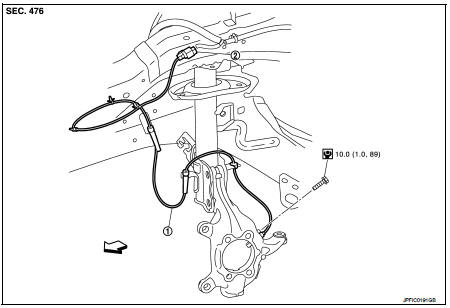
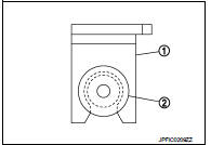
1. Front LH wheel sensor 2. Front LH wheel sensor harness connector
 : Vehicle front
 : N·m (kg-m, in-lb)
NOTE
:
Front RH wheel sensor is symmetrically opposite of LH.
Front wheel sensor : Removal and Installat
REMOVAL
1. Remove tires.
2. Remove the fender protector (front). Refer to EXT-22, "Removal and Installation".
3. Remove front wheel sensor from steering knuckle.
CAUTION:
Never rotate and never pull front wheel sensor as much as possible, when pulling
out
.
4. Remove front wheel sensor harness from the vehicle.
CAUTION:
Never twist or pull front wheel sensor harness, when removing.
INSTALLATION
Note the following, and install in the reverse order of the removal.
• Check that there is no foreign material like iron powder or damage on inner surface of front wheel sensor mounting hole of steering knuckle and sensor rotor. Install after cleaning when there are foreign material like iron powder, or replace when there is a malfunction.
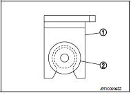
• Never twist front wheel sensor harness when installing front wheel sensor. Check that grommet (2) is fully inserted to bracket (1).
Check that front wheel sensor harness is not twisted after installation.
Rear wheel sensor : Exploded View
LEFT SIDE
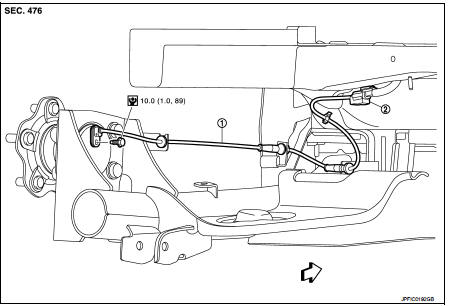
1. Rear LH wheel sensor 2. Rear LH wheel sensor harness connector
 : Vehicle front
 : N·m (kg-m, in-lb)
RIGHT SIDE
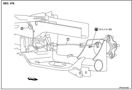
1. Rear RH wheel sensor 2. Rear RH wheel sensor harness connector
: Vehicle front
: N·m (kg-m, in-lb)
Rear wheel sensor : Removal and Installation
REMOVAL
1. Remove rear wheel sensor from wheel hub and bearing assembly.
CAUTION:
Never rotate or pull rear wheel sensor as much as possible, when pulling out.
2. Remove rear wheel sensor harness from the vehicle.
CAUTION:
Never twist and never pull rear wheel sensor harness, when removing.
INSTALLATION
Note the following, and install in the reverse order of the removal.
• Check that there is no foreign material like iron powder or damage on inner surface of rear wheel sensor mounting hole of wheel hub and bearing assembly and sensor rotor. Install after cleaning when there are foreign material like iron powder, or replace when there is a malfunction.
• Never twist rear wheel sensor harness when installing rear wheel sensor. Check that grommet (2) is fully inserted to bracket (1).
Check that rear wheel sensor harness is not twisted after installation.
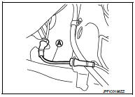
CAUTION:
Check that the identification line (A) of the rear wheel sensor
is faced upward.

 Sensor rotor
Front sensor rotor : Removal and Installation
REMOVAL
Replace wheel hub as an assembly when replacing because sensor rotor cannot
be disassembled. Refer to
FAX-43, "Removal and Installation& ...
Other materials:
Charging system preliminary inspection
Inspection Procedure
1.CHECK BATTERY TERMINALS CONNECTION
Check if battery terminals are clean and tight.
Is the inspection result normal?
YES >> GO TO 2.
NO >> Repair battery terminals connection.
2.CHECK FUSE
Check for blown fuse and fusible link.
Is the inspection resu ...
Control cable
Exploded View
1. Control cable
2. Lock plate
3. Transaxle assembly
4. Bracket A
5. Bracket B
6. CVT shift selector assembly
A: Manual lever
B: Grommet
: N·m (kg-m, ft-lb)
: N·m (kg-m, in-lb)
Removal and Installation
INSTALLATION
CAUTION:
Always apply the parking brake before p ...
Vehicle-to-vehicle distance control mode limitations
WARNING
Below are the critical operational limitations for the Intelligent Cruise Control (ICC) system in your Nissan Leaf. Operating the vehicle without strict adherence to these guidelines could result in a loss of control, leading to serious injury or death.
The ICC system is ...
