Nissan Juke Service and Repair Manual : Unlock sensor
Component Function Check
1.CHECK FUNCTION
1. Select ÔÇťDOOR LOCKÔÇŁ of ÔÇťBCMÔÇŁ using CONSULT-III.
2. Select ÔÇťLOCK STATUSÔÇŁ in ÔÇťDATA MONITORÔÇŁ mode.
3. Check that the function operates normally according to the following conditions.
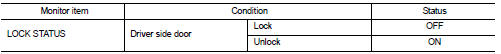
Is the inspection result normal? YES >> Unlock sensor is OK.
NO >> Refer to DLK-532, "Diagnosis Procedure".
Diagnosis Procedure
1.CHECK BCM OUTPUT SIGNAL
1. Turn ignition switch OFF.
2. Disconnect front door lock assembly (driver side) connector.
3. Check signal between front door lock assembly (driver side) harness connector and ground using oscilloscope.
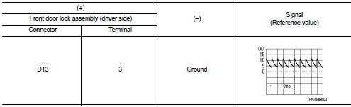
Is the inspection result normal? YES >> GO TO 3.
NO >> GO TO 2.
2.CHECK UNLOCK SENSOR CIRCUIT
1. Disconnect BCM connector.
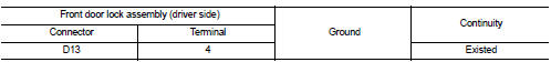
2. Check continuity between BCM harness connector and front door lock assembly (driver side) harness connector.
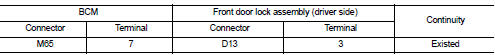
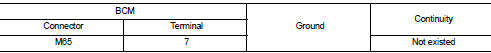
3. Check continuity between BCM harness connector and ground.
Is the inspection result normal? YES >> Replace BCM. Refer to BCS-161, "Removal and Installation".
NO >> Repair or replace harness.
3.CHECK UNLOCK SENSOR GROUND CIRCUIT
Check continuity between front door lock assembly (driver side) harness connector and ground.
Is the inspection result normal? YES >> GO TO 4.
NO >> Repair or replace harness.
4.CHECK UNLOCK SENSOR
Refer to DLK-533, "Component Inspection".
Is the inspection result normal? YES >> GO TO 5.
NO >> Replace front door lock assembly (driver side).
5.CHECK INTERMITTENT INCIDENT
Refer to GI-42, "Intermittent Incident".
>> INSPECTION END
Component Inspection
1.CHECK UNLOCK SENSOR 1. Turn ignition switch OFF.
2. Disconnect front door lock assembly (driver side) connector.
3. Check continuity between front door lock assembly (driver side) terminals.
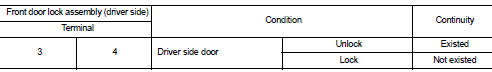
Is the inspection result normal? YES >> INSPECTION END
NO >> Replace front lock assembly (driver side).
 Remote keyless entry receiver
Component Function Check
1.CHECK FUNCTION
1. Select ÔÇťDOOR LOCKÔÇŁ of ÔÇťBCMÔÇŁ using CONSULT-III.
2. Select ÔÇťKEYLESS ÔÇŁ or ÔÇťKEYLESS UNLOCKÔÇŁ in ÔÇťDATA MONITORÔÇŁ mode.
3. Check that the f ...

Other materials:
Wheel sensor
Front wheel sensor : Exploded View
1. Front LH wheel sensor
2. Front LH wheel sensor harness connector
: Vehicle front
: N┬Ěm (kg-m, in-lb)
NOTE:
Front RH wheel sensor is symmetrically opposite of LH.
Front wheel sensor : Removal and Installat
REMOVAL
1. Remove tires.
2. Remove the fend ...
A/C auto AMP.
Reference Value
CONSULT-III DATA MONITOR REFERENCE VALUES
*: ÔÇťDUTYÔÇŁ is displayed, but voltage is indicated. Or unit is not displayed
but unit is (V).
TERMINAL LAYOUT
PHYSICAL VALUES
Fail-safe
FAIL-SAFE FUNCTION
If a communication error exists between the A/C auto amp. and multi ...
Precaution
Precaution for Supplemental Restraint System (SRS) "AIR BAG" and "SEAT
BELT
PRE-TENSIONER"
The Supplemental Restraint System such as ÔÇťAIR BAGÔÇŁ and ÔÇťSEAT BELT PRE-TENSIONERÔÇŁ,
used along
with a front seat belt, helps to reduce the risk or severity of injury to the
...
