Nissan Juke Service and Repair Manual : Unbalance steering wheel turning force (torque variation)
Description
Unbalance steering wheel turning force (torque variation).
Diagnosis Procedure
1.CHECK THE ILLUMINATION OF THE EPS WARNING LAMP
Check the EPS warning lamp while engine is running.
Does the EPS warning lamp turn OFF? YES >> GO TO 2.
NO >> Refer to STC-28, "Diagnosis Procedure".
2.CHECK STEERING COLUMN AND STEERING GEAR
Check the steering column assembly and steering gear assembly.
• Steering column assembly. Refer to ST-10, "Exploded View".
• Steering gear assembly. Refer to ST-16, "Exploded View".
Is the inspection result normal? YES >> GO TO 3.
NO >> Repair or replace the specific malfunctioning part.
3.CHECK EPS CONTROL UNIT SIGNAL
 With CONSULT-III
1. Start the engine.
CAUTION:
Never drive the vehicle.
2. Turn steering wheel from full left stop to full right stop.
3. Select “DATA MONITOR” of “EPS” and select “TORQUE SENSOR”.
4. Perform the torque sensor inspection.
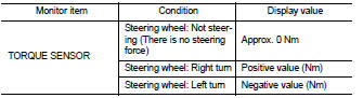
Is the inspection result normal? YES >> GO TO 5.
NO >> GO TO 4.
4.CHECK EPS MOTOR
Perform the trouble diagnosis of EPS motor. Refer to STC-22, "Diagnosis Procedure".
Is the inspection result normal? YES >> GO TO 5.
NO >> Repair or replace the specific malfunctioning part.
5.CHECK STEERING WHEEL TURNING FORCE
Check the steering wheel turning force. Refer to ST-8, "Inspection".
Is the inspection result normal? YES >> INSPECTION END
NO >> Check the steering wheel turning force for mechanical malfunction. Refer to ST-21, "Inspection".
 Unbalance steering wheel turning force and return between
right and left
Unbalance steering wheel turning force and return between
right and left
Description
Unbalance steering wheel turning force and return between right and left.
Diagnosis Procedure
1.CHECK THE ILLUMINATION OF THE EPS WARNING LAMP
Check the EPS warning lamp while engine i ...
 Removal and installation
EPS CONTROL UNIT
Removal and Installation
Never remove EPS control unit from steering column assembly. When replacing
EPS control unit, replace
steering column assembly. Refer to ST-10, "Rem ...
Other materials:
Precaution for Supplemental Restraint System (SRS) "AIR BAG" and "SEAT BELT
PRE-TENSIONER"
The Supplemental Restraint System such as “AIR BAG” and “SEAT BELT PRE-TENSIONER”,
used along
with a front seat belt, helps to reduce the risk or severity of injury to the
driver and front passenger for certain
types of collision. Information necessary to service the system safely is
...
Steering gear and linkage
Exploded View
REMOVAL
LHD Models
1. Steering gear assembly
2. Heat insulator
3. Front suspension member
: Vehicle front
: Always replace after every
disassembly.
: N·m (kg-m, ft-lb)
: N·m (kg-m, in-lb)
RHD Models
1. Steering gear assembly
2. Heat insulator
3. Front suspensio ...
Precaution Necessary for Steering Wheel Rotation after Battery Disconnect
NOTE:
• Before removing and installing any control units, first turn the ignition
switch to the LOCK position, then disconnect
both battery cables.
• After finishing work, confirm that all control unit connectors are connected
properly, then re-connect both
battery cables.
• Always us ...
