
Nissan Leaf 2018-2025 (ZE1) Owner's Manual : System operation
The system provides both visual and audible feedback regarding rearward obstacles whenever the shift lever is placed into the R (Reverse) position.
Sonar Operation Table
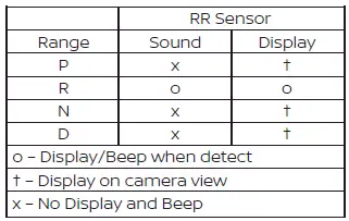
For safety and stability, the RSS is automatically deactivated when your speed exceeds 6 mph (10 km/h) and will reactivate once you drop below that threshold.
If an obstacle is detected exclusively by the corner sensors and you remain stationary, the intermittent tone will automatically cease after 3 seconds. The audible alert will also stop if you steer the Nissan Leaf away from the object or if the object itself moves out of the detection zone.
When an object enters the detection range, a green indicator appears and begins to blink in synchronization with an intermittent tone. As you move closer, the indicator shifts to yellow and the blinking frequency increases. Finally, when you are in very close proximity to the obstacle, the indicator turns red, the blinking stops, and the tone becomes a continuous warning.
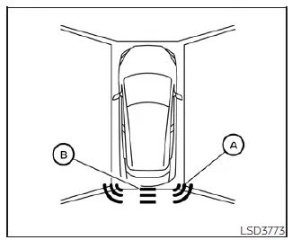
The system distinguishes between detection zones: indicator A illuminates when the corner of your Nissan Leaf approaches an object, while indicator B signifies that the center of the rear bumper is nearing an object.
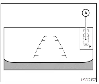
The system indicators labeled A will dynamically appear and update as you progressively move the vehicle closer to a detected object.
 Rear sonar system (RSS)
The Rear Sonar System (RSS) is designed to enhance your parking confidence by providing audible tones that alert you to the presence of obstacles located near the rear bumper of ...
 How to enable/disable the rear sonar system
The Rear Sonar System in your Nissan Leaf is designed for seamless operation, automatically activating whenever the power switch is in the ON position and the shift lever is move ...
Other materials:
Wheel alignment
Inspection
DESCRIPTION
CAUTION:
• The adjustment mechanisms of camber, caster, and kingpin inclination angles
are not included.
• If camber, caster, or kingpin inclination angle is outside the standard, check
front suspension parts
for wear and damage. Replace suspect parts if a malfunc ...
Compressor dose dot operate
Description
SYMPTOM
Compressor dose not operate.
Diagnosis Procedure
NOTE:
• Perform self-diagnoses with CONSULT-III before performing symptom diagnosis.
If any DTC is detected,
perform the corresponding diagnosis.
• Check that refrigerant is enclosed in cooler cycle normally. If refrig ...
Precaution for Supplemental Restraint System (SRS) "AIR BAG" and "SEAT BELT
PRE-TENSIONER"
The Supplemental Restraint System such as “AIR BAG� and “SEAT BELT PRE-TENSIONER�,
used along
with a front seat belt, helps to reduce the risk or severity of injury to the
driver and front passenger for certain
types of collision. Information necessary to service the system safely is
...
