Nissan Juke Service and Repair Manual : System
System Diagram
System Description
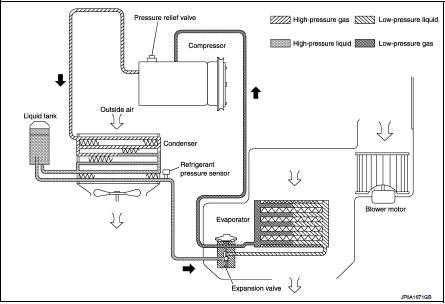
REFRIGERANT CYCLE
Refrigerant Flow
The refrigerant from the compressor, flows the condenser with liquid tank, the
evaporator, and returns to the
compressor. The refrigerant evaporation in the evaporator is controlled by an
expansion valve.
Freeze Protection
Automatic air conditioner • When intake sensor detects that evaporator surface temperature is 2°C (36°F) or less, A/C auto amp.
requests BCM to turn the compressor OFF.
• BCM requests ECM to turn the compressor to OFF by the signal from A/C auto amp., and ECM makes A/C relay to OFF, and stops the compressor.
Manual air conditioner
• When thermo control amp. detects that evaporator surface temperature becomes
2°C (36°F) or less, BCM
requests ECM to turn the compressor OFF, and stops the compressor.
REFRIGERANT SYSTEM PROTECTION
Refrigerant Pressure Sensor • The refrigerant system is protected against excessively high- or low-pressures by the refrigerant pressure sensor, installed at the condenser exit. The refrigerant pressure sensor detects the pressure inside the refrigerant line and sends the voltage signal to the ECM if the system pressure rises above, or falls below the specifications.
• ECM turns the A/C relay to OFF and stops the compressor when the high-pressure side detected by refrigerant pressure sensor is following conditions;
- Approximately 3,120 kPa (31.2 bar, 31.8 kg/cm2, 452 psi) or more (Engine
speed is less than 1,500 rpm.)
- Approximately 2,740 kPa (27.4 bar, 27.9 kg/cm2, 397 psi) or more (Engine speed
is 1,500 rpm or more.)
- Approximately 120 kPa (1.2 bar, 1.2 kg/cm2, 17 psi) or less
Pressure Relief Valve The refrigerant system is also protected by a pressure relief valve, located in the rear head of the compressor.
The release port on the pressure relief valve automatically opens and releases refrigerant into the atmosphere when the pressure of refrigerant in the system increases to an unusual level [more than 3,800 kPa (38 bar, 38.8 kg/cm2, 551 psi)].
 Component parts
Component Parts Location
1. Expansion valve
2. Condenser
3. Compressor
4. Refrigerant pressure sensor
5. Liquid tank
6. Evaporator
A. Built-in heater & cooling unit assembly
Componen ...
 Basic inspection
...
Other materials:
Clutch master cylinder
LHD : Exploded View
1. Reservoir hose
2. Reservoir tank
3. Master cylinder
LHD : Removal and Installation
REMOVAL
CAUTION:
• Keep painted surface on the body or other parts free of clutch fluid. If it
spills, wipe up immediately
and wash the affected area with water.
• Never disas ...
How to enable/disable the RCTA system
Follow these steps to customize or toggle the RCTA system settings:
1. Press the button repeatedly until "Settings" appears on the vehicle information display.
Use the button to navigate to "Driver Assistance," then press the OK button to enter the s ...
Door mirror system (without intelligent key)
LHD
LHD : Wiring Diagram
For connector terminal arrangements, harness layouts, and alphabets in a
(option abbreviation; if not
described in wiring diagram), refer to GI-12, "Connector Information/Explanation
of Option Abbreviation".
RHD
RHD : Wiring Diagram
For connector termina ...
