Nissan Juke Service and Repair Manual : Steering switch signal B circuit
Description
Transmits the steering switch signal to audio unit.
Diagnosis Procedure
1.CHECK STEERING SWITCH SIGNAL B CIRCUIT
1. Disconnect audio unit connector and spiral cable connector.
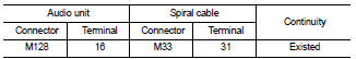
2. Check continuity between audio unit harness connector and spiral cable harness connector.
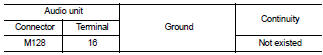
3. Check continuity between audio unit harness connector and ground.
Is the inspection result normal? YES >> GO TO 2.
NO >> Repair harness or connector.
2.CHECK SPIRAL CABLE
Check spiral cable.
Is the inspection result normal? YES >> GO TO 3.
NO >> Replace spiral cable. Refer to SR-16, "Exploded View".
3.CHECK AUDIO UNIT VOLTAGE
1. Connect audio unit connector and spiral cable connector.
2. Turn ignition switch ON.
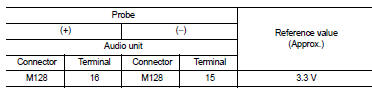
3. Check voltage between audio unit harness connector.
Is the inspection result normal? YES >> GO TO 4.
NO >> Replace audio unit. Refer to AV-38, "Removal and Installation".
4.CHECK STEERING SWITCH
1. Turn ignition switch OFF.
2. Check steering switch. Refer to AV-30, "Component Inspection".
Is the inspection result normal? YES >> INSPECTION END
NO >> Replace steering switch. Refer to AV-44, "Exploded View".
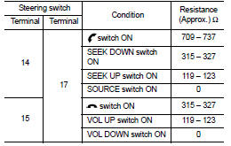
Component Inspection
Measure the resistance between the steering switch connector.
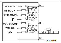
Standard
 Steering switch signal a circuit
Description
Transmits the steering switch signal to audio unit.
Diagnosis Procedure
1.CHECK STEERING SWITCH SIGNAL A CIRCUIT
1. Disconnect audio unit connector and spiral cable connector.
2. Chec ...
 Steering switch ground circuit
Description
Transmits the steering switch signal to audio unit.
Diagnosis Procedure
1.CHECK STEERING SWITCH SIGNAL GROUND CIRCUIT
1. Disconnect audio unit connector and spiral cable connector.
2. ...
Other materials:
High voltage precautions
High-voltage components
WARNING
The advanced electric vehicle (EV) system in your Nissan Leaf operates using high-voltage electricity, reaching levels up to approximately 400 volts DC. Please be aware that these internal components can remain extremely hot during operation, immed ...
Rear suspension beam
Exploded View
1. Rear suspension beam
2. Rear suspension arm bracket
: Always replace after every
disassembly.
: N·m (kg-m, ft-lb)
Removal and Installation
REMOVAL
1. Remove tires. Refer to WT-7, "Removal and Installation".
2. Drain brake fluid. Refer to BR-12, "Draining ...
Seat belt extenders
If, because of body size or driving position, it is not possible to properly
fit the lap-shoulder belt and fasten it, an extender that is compatible with the
installed seat belts is available that can be purchased. The extender adds approximately
8 in (200 mm) of length and may be used for eit ...
