Nissan Juke Service and Repair Manual : Side turn signal lamp
Exploded View
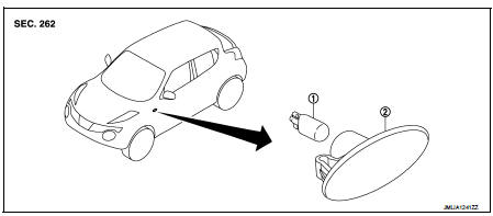
1. Side turn signal lamp bulb 2. Side turn signal lamp hous
Removal and Installation
CAUTION:
Disconnect battery negative terminal or remove the fuse.
REMOVAL
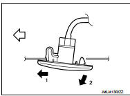
1. Remove the side turn signal lamp in numerical order shown in
the figure.
2. Rotate the bulb socket counterclockwise and unlock it.
NOTE
:
Support side turn signal lamp harness with tape so that it won't fall
into the front fender.
 : Vehicle front (side turn
signal lamp LH)
 : Vehicle rear (side turn signal
lamp RH)
INSTALLATION
1. Rotate the bulb socket clockwise and lock it.
2. Fix the pawl-side behind the side turn signal lamp housing first, then push the resin clip-side.
Replacement
CAUTION:
ŌĆó Disconnect the battery negative terminal or the fuse.
ŌĆó Never touch the glass of bulb directly by hand. Keep grease and other oily matters away from it.
ŌĆó Never touch bulb by hand while it is lit or right after being turned off.
ŌĆó Never leave bulb out of lamp reflector for a long time because dust, moisture smoke, etc. may affect the performance of lamp. When replacing bulb, be sure to replace it with new one
.
SIDE TURN SIGNAL LAMP BULB
1. Remove side turn signal lamp. Refer to EXL-98, "Removal and Installation".
2. Remove bulb from the bulb socket.
 Hazard switch
Exploded View
1. Instrument panel assembly
2. Hazard switch
: Pawl
Removal and Installation
REMOVAL
1. Remove Audio unit. Refer to AV-38, "Removal and Installation".
2. Disengage f ...
 Headlamp aiming switch
Exploded View
1. Headlamp aiming switch
2. Instrument lower panel assembly LH
: Pawl
Removal and Installation
REMOVAL
1. Remove instrment lower panel (LH/RH). Refer to IP-13, "Removal an ...
Other materials:
Rear seat (4WD)
Exploded View
1. Seatback board RH
2. Headrest
3. Headrest holder (locked)
4. Headrest holder (free)
5. Seatback trim RH
6. Seatback pad RH
7. Seatback lock knob
8. Seatback lock knob finisher
9. Seatback lock assembly RH
10. Seat lock cover RH
11. Bush
12. Side hinge
13. Spac ...
Tow Truck Towing
CAUTION:
ŌĆó All applicable state or Provincial laws and local laws regarding the towing
operation must be
obeyed.
ŌĆó It is necessary to use proper towing equipment to avoid possible damage to the
vehicle during towing
operation. Towing is in accordance with Towing Procedure Manual at deale ...
Liquid Gasket
REMOVAL OF LIQUID GASKET SEALING
ŌĆó After removing mounting nuts and bolts, separate the mating surface
using the seal cutter [SST: KV10111100] (A) and remove old
liquid gasket sealing.
CAUTION:
Be careful not to damage the mating surfaces.
ŌĆó Tap the seal cutter [SST: KV10111100] to inser ...
