Nissan Juke Service and Repair Manual : Primary speed sensor
Exploded View
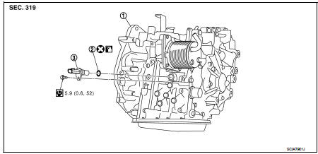
1. Transaxle assembly
2. O-ring
3. Primary speed sensor
 : Always replace after every
disassembly.
 : N·m (kg-m, in-lb)
 : Genuine NISSAN CVT Fluid NS-2
Removal and Installation
REMOVAL
1. Remove the battery. Refer to PG-124, "Removal and Installation".
2. Remove ECM bracket. Refer to EC-447, "Removal and Installation".
3. Remove primary speed sensor connector.
4. Remove primary speed sensor.
5. Remove O-ring from primary speed sensor.
INSTALLATION
Note the following, and install in the reverse order of removal.
CAUTION:
• Never reuse O-ring.
• Apply CVT fluid to O-ring.
Inspection and Adjustment
INSPECTION AFTER INSTALLATION
Check for CVT fluid leakage. Refer to TM-480, "Inspection".
ADJUSTMENT AFTER INSTALLATION
Adjust the CVT fluid level. Refer to TM-379, "Adjustment".
 Control valve
Exploded View
COMPONENT PARTS LOCATION
1. Transaxle assembly
2. Control valve
3. Bracket
4. O-ring
5. Oil strainer assembly
6. Magnet
7. Drain plug gasket
8. Drain plug
9. Oil pan mo ...
 Secondary speed sensor
Exploded View
1. Transaxle assembly
2. Secondary speed sensor
3. O-ring
: Always replace after every
disassembly.
: N·m (kg-m, in-lb)
: Genuine NISSAN CVT Fluid NS-2
Removal and Installa ...
Other materials:
Wiring diagram
IPDM E/R
Wiring Diagram
For connector terminal arrangements, harness layouts, and alphabets in a
(option abbreviation; if not
described in wiring diagram), refer to GI-12, "Connector Information/Explanation
of Option Abbreviation".
...
P1564 ASCD steering switch
DTC Logic
DTC DETECTION LOGIC
NOTE:
If DTC P1564 is displayed with DTC P0605, first perform the trouble diagnosis
for DTC P0605. Refer to
EC-683, "DTC Logic".
DTC CONFIRMATION PROCEDURE
1.PRECONDITIONING
If DTC Confirmation Procedure has been previously conducted, always turn
...
Brake fluid
Inspection
BRAKE FLUID LEVEL
• Check that the fluid level in the reservoir tank is within the specified
range (MAX – MIN lines).
• Visually check for any brake fluid leakage around the reservoir
tank.
• Check the brake system for any leakage if the fluid level is
extremely low (lower ...
