Nissan Juke Service and Repair Manual : P2263 TC system
DTC Logic
DTC DETECTION LOGIC

Diagnosis Procedure
1.CHECK VACUUM HOSES AND VACUUM GALLERY
1. Turn ignition switch OFF.
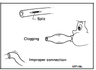
2. Check vacuum hoses and vacuum gallery for clogging, cracks or improper connection. Refer to EC-825, "TURBOCHARGER BOOST CONTROL : Vacuum Hose Drawing".
Is the inspection result normal? Yes >> Repair or replace.
No >> GO TO 2.

2.CHECK AIR FILTER
Check that air filter is not obstructed.
Is the inspection result normal? Yes >> Repair or replace.
No >> GO TO 3.
3.CHECK INTAKE AIR DUCT
Check that intake air duct is not obstructed.
Is the inspection result normal? Yes >> Repair or replace.
No >> GO TO 4.
4.CHECK VACUUM PUMP
Check vacuum pump.
Is the inspection result normal? Yes >> Repair or replace.
No >> GO TO 5.
5.CHECK TURBOCHARGER
Check turbocharger.
Is the inspection result normal? Yes >> Repair or replace.
No >> GO TO 6.
6.CHECK EGR COOLER BYPASS CONTROL SOLENOID VALVE POWER SUPPLY CIRCUIT
1. Disconnect EGR cooler bypass control solenoid valve harness connector.
2. Turn ignition switch ON.
3. Check the voltage between EGR cooler bypass control solenoid valve harness connector and ground.

Is the inspection result normal? YES >> GO TO 8.
NO >> GO TO 7.
7.DETECT MALFUNCTIONING PART
Check the following.
• Harness connectors E8, F1 • Harness for open or short between IPDM E/R and EGR cooler bypass control solenoid valve
>> Repair open circuit or short to ground or short to power in harness or connectors.
8.CHECK EGR COOLER BYPASS CONTROL SOLENOID VALVE OUTPUT SIGNAL CIRCUIT FOR OPEN AND SHORT
1. Turn ignition switch OFF.
2. Disconnect ECM harness connector.
3. Check the continuity between EGR cooler bypass control solenoid valve harness connector and ECM harness connector.

4. Also check harness for short to ground and short to power.
Is the inspection result normal? YES >> GO TO 9.
NO >> Repair open circuit or short to ground or short to power in harness or connectors.
9.CHECK EGR COOLER BYPASS CONTROL SOLENOID VALVE
Refer to EC-894, "Component Inspection".
Is the inspection result normal? YES >> GO TO 10.
NO >> Replace turbocharger boost control solenoid valve.
10.CHECK TURBOCHARGER BOOST SENSOR
Refer to EC-912, "Component Inspection".
Is the inspection result normal? YES >> GO TO 11.
NO >> Replace turbocharger boost sensor.
11.CHECK THROTTLE CONTROL MOTOR
Refer to EC-998, "Component Inspection".
Is the inspection result normal? YES >> GO TO 12.
NO >> Replace electric throttle control actuator.
12.CHECK INTERMITTENT INCIDENT
Refer to GI-42, "Intermittent Incident", ???INCIDENT SIMULATION TESTS??? and ???GROUND INSPECTION???.
>> INSPECTION END
 P2226 baro sensor
DTC Logic
DTC DETECTION LOGIC
Diagnosis Procedure
1.REPLACE ECM
Perform EC-879, "Work Procedure".
>> INSPECTION END ...
 P245A EGR cooler bypass valve control solenoid valve
DTC Logic
DTC DETECTION LOGIC
NOTE:
If DTC P245A is displayed with DTC P0560 or P0657, first perform trouble
diagnosis for DTC P0560 or P0657.
Refer to EC-963, "DTC Logic" (DTC P05 ...
Other materials:
B210E starter relay
DTC Logic
DTC DETECTION LOGIC
NOTE:
• If DTC B210E is displayed with DTC U1000, first perform the trouble diagnosis
for DTC U1000. Refer to
PCS-59, "DTC Logic".
• If DTC B210E is displayed with DTC B209F, first perform the trouble diagnosis
for DTC B209F. Refer to
SEC-209, " ...
Rear stabilizer
Exploded View
1. Stabilizer bar
2. Bushing
3. Stabilizer clamp
4. Stabilizer link
5. Lower link
6. Rear suspension member
: Vehicle front
: Always replace after every
disassembly.
: N·m (kg-m, ft-lb)
Removal and Installation
REMOVAL
1. Remove stabilizer link.
2. Remove center pi ...
Unlock sensor
Component Function Check
1.CHECK FUNCTION
1. Select “INTELLIGENT KEY” of “BCM” using CONSULT-III.
2. Select “UNLK SEN -DR” in “DATA MONITOR” mode.
3. Check that the function operates normally according to the following
conditions.
Is the inspection result normal?
YES >> Unlock sensor ...
