Nissan Juke Service and Repair Manual : P1777 step motor
DTC Logic
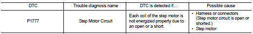
DTC DETECTION LOGIC
DTC CONFIRMATION PROCEDURE
CAUTION:
Always drive vehicle at a safe speed.
NOTE:
If ‚ÄúDTC CONFIRMATION PROCEDURE‚ÄĚ has been previously performed, always turn ignition switch OFF and wait at least 10 seconds before performing the next test.
After the repair, perform the following procedure to confirm the malfunction is eliminated.
1.CHECK DTC DETECTION
 With CONSULT-III
1. Turn ignition switch ON.
2. Drive vehicle for at least 5 consecutive seconds.
3. Select ‚ÄúSelf Diagnostic Results‚ÄĚ in ‚ÄúTRANSMISSION‚ÄĚ.
 With GST
Follow the procedure ‚ÄúWith CONSULT-III‚ÄĚ.
Is ‚ÄúP1777‚ÄĚ detected? YES >> Go to TM-250, "Diagnosis Procedure".
NO >> Check intermittent incident. Refer to GI-42, "Intermittent Incident".
Diagnosis Procedure
1.CHECK INPUT SIGNALS
With CONSULT-III
1. Start engine.
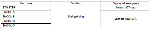
2. Select ‚ÄúDATA MONITOR‚ÄĚ.
3. Start vehicle and read out the value of ‚ÄúSTM STEP‚ÄĚ, ‚ÄúSMCOIL A‚ÄĚ, ‚ÄúSMCOIL B‚ÄĚ, ‚ÄúSMCOIL C‚ÄĚ, and ‚ÄúSMCOIL D‚ÄĚ.
Is the inspection result normal? YES >> GO TO 4.
NO >> GO TO 2.
2.CHECK HARNESS BETWEEN TCM AND STEP MOTOR
1. Turn ignition switch OFF.
2. Disconnect CVT unit harness connector and TCM connector.
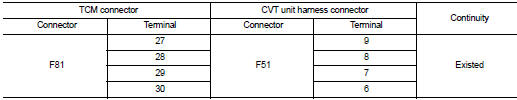
3. Check continuity between TCM connector terminals and CVT unit harness connector terminals.
4. If OK, check harness for short to ground and short to power.
5. If OK, check continuity between body ground and transaxle assembly.
6. Reinstall any part removed.
Is the inspection result normal? YES >> GO TO 3.
NO >> Repair or replace damaged parts.
3.CHECK STEP MOTOR
Check step motor. Refer to TM-251, "Component Inspection".
Is the inspection result normal? YES >> GO TO 4.
NO >> Repair or replace damaged parts.
4.CHECK TCM
Check TCM input/output signals. Refer to TM-164, "Reference Value".
Is the inspection result normal? YES >> Check intermittent incident. Refer to GI-42, "Intermittent Incident".
NO >> Replace the TCM. Refer to TM-280, "Removal and Installation".
Component Inspection
STEP MOTOR
1.STEP MOTOR
1. Turn ignition switch OFF.
2. Disconnect CVT unit harness connector.
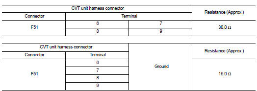
3. Check resistance between CVT unit harness connector terminals and ground.
Is the inspection result normal? YES >> INSPECTION END
NO >> Replace the transaxle assembly. Refer to TM-301, "Removal and Installation".
 P1745 line pressure control
Description
The line pressure solenoid valve regulates the oil pump discharge pressure to
suit the driving condition in
response to a signal sent from the TCM.
DTC Logic
DTC DETECTION LOGIC
D ...
 P1778 step motor
Description
‚ÄĘ The step motor's 4 aspects of ON/OFF change according to the signal from
TCM. As a result, the flow of line
pressure to primary pulley is changed and pulley ratio is controlled.
‚ ...
Other materials:
HR16DE : Inspection and Adjust
INSPECTION
Magnetic Switch Check
‚ÄĘ Before starting to check, disconnect the battery cable from the negative
terminal.
‚ÄĘ Disconnect ‚ÄúM‚ÄĚ terminal of starter motor.
1. Continuity test [between ‚ÄúS‚ÄĚ terminal (A) and switch body]
B : ‚ÄúB‚ÄĚ terminal
C : ‚ÄúM‚ÄĚ terminal
‚ÄĘ Replace ...
ECU diagnosis information
ECM
Reference Value
TERMINAL LAYOUT
PHYSICAL VALUES
NOTE:
‚ÄĘ ECM is located in the engine room left side near battery.
‚ÄĘ When disconnecting ECM harness connector (1), loosen (B) it with
levers as far as they will go as shown in the figure.
2 : ECM
A : Fasten
‚ÄĘ Pulse signal is measur ...
Mirrors
Manual anti-glare rearview mirror
Flip the lower adjustment tab forward into the designated night position 1 to significantly dim the harsh reflection and reduce glare caused by the high-beam headlights of trailing vehicles behind you at night.
Push the tab ...
