Nissan Juke Service and Repair Manual : P1650 thermoplunger control unit
DTC Logic
DTC DETECTION LOGIC
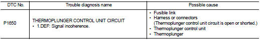
Diagnosis Procedure
1.CHECK THERMOPLUNGER CONTROL UNIT POWER SUPPLY CIRCUIT
1. Turn ignition switch OFF.
2. Disconnect thermoplunger control unit harness connector.
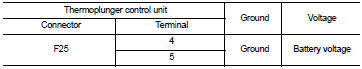
3. Check the voltage between thermoplunger control unit harness connector and ground.
Is the inspection result normal? YES >> GO TO 3.
NO >> GO TO 2.
2.DETECT MALFUNCTIONING PART
Check the following.
• 100A fusible link (letter B) • Harness for open and short between thermoplunger control unit and battery
>> Repair open circuit or short to ground or short to power in harness or connectors.
3.CHECK THERMOPLUNGER CONTROL UNIT SIGNAL CIRCUIT FOR OPEN AND SHORT-I
1. Disconnect ECM harness connector.
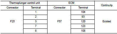
2. Check the continuity between thermoplunger control unit harness connector and ECM harness connector.
3. Also check harness for short to ground and short to power.
Is the inspection result normal? YES >> GO TO 5.
NO >> GO TO 4.
4.DETECT MALFUNCTIONING PART
Check the following.
• Harness for open or short between thermoplunger control unit and ECM.
>> Repair open circuit or short to ground or short to power in harness or connectors.
5.CHECK THERMOPLUNGER CONTROL UNIT SIGNAL CIRCUIT FOR OPEN AND SHORT-II
1. Disconnect thermoplunger harness connector.
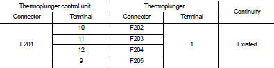
2. Check the continuity between thermoplunger control unit harness connector and thermoplunger harness connector.
3. Also check harness for short to ground and short to power.
Is the inspection result normal? YES >> GO TO 6.
NO >> Repair open circuit or short to ground or short to power in harness or connectors.
6.CHECK THERMOPLUNGER
Refer to EC-994, "Component Inspection".
Is the inspection result normal? YES >> GO TO 7.
NO >> Replace malfunctioning Thermoplunger.
7.CHECK INTERMITTENT INCIDENT
Refer to GI-42, "Intermittent Incident".
Is the inspection result normal? YES >> Replace thermoplunger control unit.
NO >> Repair or replace.
Component Inspection
1.CHECK THERMOPLUNGER
1. Turn ignition switch OFF.
2. Disconnect thermoplunger harness connector.
3. Check resistance between thermoplunger terminals as follows.
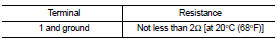
Is the inspection result normal? YES >> INSPECTION END
NO >> Replace malfunctioning thermoplunger.
 P1643 thermoplunger control unit
DTC Logic
DTC DETECTION LOGIC
Diagnosis Procedure
1.CHECK THERMOPLUNGER CONTROL UNIT POWER SUPPLY CIRCUIT
1. Turn ignition switch OFF.
2. Disconnect thermoplunger control unit harness connector ...
 P2002 diesel particulate filter
DTC Logic
DTC DETECTION LOGIC
Diagnosis Procedure
1.CHECK DIESEL PARTICULATE FILTER
Refer to EC-995, "Component Inspection".
OK or NG
OK >> INSPECTION END
NG >> GO TO ...
Other materials:
Water outlet
Exploded View
1. Engine coolant temperature sensor
2. Clamp
3. Gasket
4. Clamp
5. Bracket
6. Clamp
7. Water outlet
8. Clamp
9. Clamp
10. Washer
A. To electric throttle control actuator
B. To radiator
C. To CVT oil warmer
D. To heater core
E. To electric throttle control act ...
Engine block heater (if so equipped)
Engine block heaters are used to assist in cold temperature starting.
The engine block heater should be used when the outside temperature is 208F (−78C)
or lower.
To use the engine block heater
1. Turn the engine off.
2. Open the hood and unwrap the engine block heater cord.
3. Plug the ...
Power supply and ground circuit
Diagnosis Procedure
1.CHECK 4WD CONTROL MODULE POWER SUPPLY (1)
1. Turn the ignition switch OFF.
2. Disconnect 4WD control module harness connector.
3. Check the voltage between 4WD control module harness connector and ground.
4. Turn the ignition switch ON.
CAUTION:
Never start the engin ...
