Nissan Juke Service and Repair Manual : P1220 fuel pump control module (FPCM)
DTC Logic
DTC DETECTION LOGIC
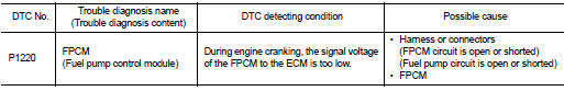
DTC CONFIRMATION PROCEDURE
1.PRECONDITIONING
1. Turn ignition switch OFF and wait at least 10 seconds.
2. Turn ignition switch ON.
3. Turn ignition switch OFF and wait at least 10 seconds.
TESTING CONDITION:
• Before performing the following procedure, confirm that battery voltage is
between 12 - 15 V at idle.
• Before performing the following procedure, check that the engine coolant temperature is −10°C (14°F) or more.
>> GO TO 2.
2.PERFORM DTC CONFIRMATION PROCEDURE
1. Start engine and let it idle for at least 5 seconds.
If engine does not start, crank engine for at least 5 seconds.
2. Check DTC.
Is DTC detected? YES >> Proceed to EC-323, "Diagnosis Procedure".
NO >> INSPECTION END
Diagnosis Procedure
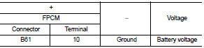
1.CHECK FPCM POWER SUPPLY
1. Turn ignition switch OFF.
2. Disconnect FPCM harness connector.
3. Turn ignition switch ON.
4. Check the voltage between FPCM harness connector and ground.
Is the inspection result normal? YES >> GO TO 2.
NO >> GO TO 3.
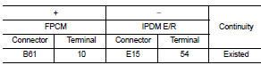
2.CHECK FPCM POWER SUPPLY CIRCUIT
1. Turn ignition switch OFF.
2. Disconnect IPDM E/R harness connector.
3. Check the continuity between FPCM harness connector and IPDM E/R harness connector.
4. Also check harness for short to ground.
Is the inspection result normal? YES >> Perform the trouble diagnosis for power supply circuit.
NO >> Repair or replace error-detected parts.
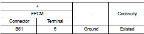
3.CHECK FPCM GROUND CIRCUIT
1. Turn ignition switch OFF.
2. Check the continuity between FPCM harness connector and ground.
3. Also check harness for short to power.
Is the inspection result normal? YES >> GO TO 4.
NO >> Repair or replace error-detected parts.
4.CHECK FPCM INPUT AND OUTPUT CIRCUITS
1. Disconnect ECM harness connector.
2. Check the continuity between FPCM harness connector and ECM harness connector
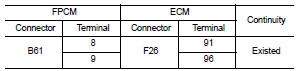
3. Also check harness for short to ground and to power.
Is the inspection result normal? YES >> GO TO 5.
NO >> Repair or replace error-detected parts.
5.CHECK FUEL PUMP CONTROL CIRCUIT
1. Disconnect fuel level sensor unit (fuel pump) harness connector.
2. Check the continuity between FPCM harness connector and fuel level sensor unit (fuel pump) harness connector.
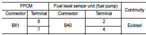
3. Also check harness for short to ground and to power.
Is the inspection result normal? YES >> GO TO 6.
NO >> Repair or replace error-detected parts.
6.CHECK FPCM
Check the FPCM. Refer to EC-325, "Component Inspection (FPCM)".
Is the inspection result normal? YES >> Check intermittent incident .Refer to GI-42, "Intermittent Incident".
NO >> Replace FPCM. Refer to EC-448, "Removal and Installation".
Component Inspection (FPCM)
1.CHECK FUEL PUMP CONTROL MODULE (FPCM)
Check the voltage between FPCM terminals as per the following conditions.

Is the inspection result normal? YES >> INSPECTION END
NO >> Replace FPCM. Refer to EC-448, "Removal and Installation".
 P1217 engine over temperature
DTC Logic
DTC DETECTION LOGIC
NOTE:
• If DTC P1217 is displayed with DTC UXXXX, first perform the trouble diagnosis
for DTC UXXXX.
• If DTC P1217 is displayed with DTC P0607, first perform t ...
 P1225 TP sensor
DTC Logic
DTC DETECTION LOGIC
DTC CONFIRMATION PROCEDURE
1.PRECONDITIONING
If DTC Confirmation Procedure has been previously conducted, always perform
the following procedure
before conductin ...
Other materials:
P0487 EGR volume control valve
DTC Logic
DTC DETECTION LOGIC
Diagnosis Procedure
1.CHECK EGR VOLUME CONTROL VALVE CONTROL CIRCUIT
1. Turn ignition switch OFF.
2. Disconnect EGR volume control valve harness connector and ECM harness
connector.
3. Check the continuity between EGR volume control valve terminal harness
co ...
Component parts
Charging system
CHARGING SYSTEM : Component Parts Location
1. Charge warning lamp (On the combination
meter)
2. Alternat
CHARGING SYSTEM : Component Description
Power generation voltage variable control system
POWER GENERATION VOLTAGE VARIABLE CONTROL SYSTEM : Component
Parts Location
N ...
B26F2 ignition relay
DTC Logic
DTC DETECTION LOGIC
DTC CONFIRMATION PROCEDURE
1.PERFORM DTC CONFIRMATION PROCEDURE
1. Turn ignition switch ON under the following conditions, and wait for 2
seconds or more.
CVT models
- Selector lever is in the P or N position
- Do not depress brake pedal
M/T models
- Do n ...
