Nissan Juke Service and Repair Manual : Luggage room lamp circuit
Description
Controls the luggage room lamp (ground side) to turn the luggage room lamp ON and OFF.
Diagnosis Procedure
CAUTION:
Before performing the diagnosis, check that the following are normal.
• Interior room lamp power supply • Luggage room lamp bulb
1.CHECK LUGGAGE ROOM LAMP OUTPUT
1. Turn ignition switch OFF.
2. Remove the luggage room lamp bulb.
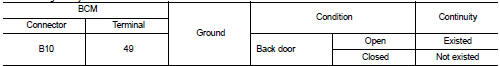
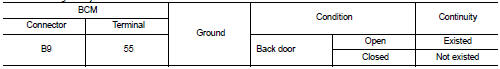
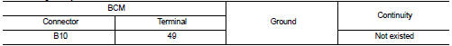
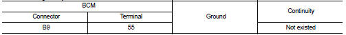
3. Check continuity between BCM harness connector and ground.
With Intelligent Key
Without Intelligent Key
Is the inspection result normal? YES >> GO TO 2.
Fixed ON>>GO TO 3.
Fixed OFF>>Replace BCM. Refer to BCS-93, "Removal and Installation".
2.CHECK LUGGAGE ROOM LAMP OPEN CIRCUIT
1. Disconnect BCM connector.
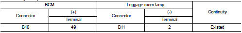
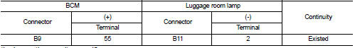
2. Check continuity between BCM harness connector and luggage room lamp harness connector.
With Intelligent Key
Without Intelligent Key
Is the inspection result normal? YES >> Replace luggage room lamp.
NO >> Repair or replace harnesses.
3.CHECK LUGGAGE ROOM LAMP SHORT CIRCUIT
1. Disconnect BCM connector.
2. Check continuity between BCM harness connector and ground.
With Intelligent Key
Without Intelligent Key
Is the inspection result normal? YES >> Replace BCM. Refer to BCS-93, "Removal and Installation".
NO >> Repair or replace harnesses.
 Interior room lamp control circuit
Description
Controls each interior room lamp (ground side) by PWM signal.
NOTE:
PWM signal control period is approximately 250 Hz (in the gradual
brightening/dimming).
Component Function Check ...
 Push-button ignition switch illumination circuit
Description
Provides the power supply and the ground to control the push-button ignition
switch illumination.
Component Function Check
1.CHECK PUSH-BUTTON IGNITION SWITCH ILLUMINATION OPERATION
...
Other materials:
Component parts
INTERIOR LIGHTING SYSTEM
INTERIOR LIGHTING SYSTEM : Component Parts Location
1. IPDM E/R
Refer to PCS-5, "Component Parts
Location"
2. BCM
Refer to BCS-6, "BODY CONTROL
SYSTEM : Component Parts Location"
3. Door lock and unlock switch
4. Front door request switch (driv ...
Wiring diagram
IPDM E/R
Wiring Diagram
For connector terminal arrangements, harness layouts, and alphabets in a
(option abbreviation; if not
described in wiring diagram), refer to GI-12, "Connector Information/Explanation
of Option Abbreviation".
...
ECM branch line circuit
Diagnosis Procedure
1.CHECK CONNECTOR
1. Turn the ignition switch OFF.
2. Disconnect the battery cable from the negative terminal.
3. Check the terminals and connectors of the ECM for damage, bend and loose
connection (unit side and
connector side).
Is the inspection result normal?
YES &g ...
