Nissan Juke Service and Repair Manual : P0962 pressure control solenoid A
DTC Logic
DTC DETECTION LOGIC
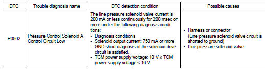
DTC CONFIRMATION PROCEDURE
1.PREPARATION BEFORE WORK
If another "DTC CONFIRMATION PROCEDURE" occurs just before, turn ignition switch OFF and wait for at least 10 seconds, then perform the next test.
>> GO TO 2.
2.CHECK DTC DETECTION
1. Start the engine and wait for 5 seconds or more.
2. Check the first trip DTC.
Is “P0962” detected? YES >> Go to TM-431, "Diagnosis Procedure".
NO >> INSPECTION END
Diagnosis Procedure
1.CHECK CIRCUIT BETWEEN TCM AND THE CVT UNIT
1
. Turn ignition switch OFF.
2. Disconnect the TCM connector and the CVT unit connector.
3. Check the continuity between TCM harness connector terminal and ground.
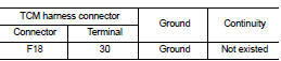
Is the inspection result normal? YES >> GO TO 2.
NO >> Repair or replace the malfunctioning parts.
2.CHECK LINE PRESSURE SOLENOID VALVE
Check the line pressure solenoid valve. Refer to TM-431, "Component Inspection (Line Pressure Solenoid Valve)".
Is the inspection result normal? YES >> Check intermittent incident. Refer to GI-42, "Intermittent Incident".
NO >> Repair or replace the malfunctioning parts.
Component Inspection (Line Pressure Solenoid Valve)
1.CHECK LINE PRESSURE SOLENOID VALVE
Check the resistance between the CVT unit connector terminal and ground.
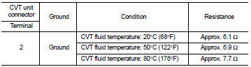
Is the inspection result normal? YES >> INSPECTION END
NO >> There is a malfunction of the line pressure solenoid valve. Replace the transaxle assembly. Refer to TM-508, "Removal and Installation".
 P0863 TCM communication
DTC Logic
DTC DETECTION LOGIC
DTC CONFIRMATION PROCEDURE
1.PREPARATION BEFORE WORK
If another "DTC CONFIRMATION PROCEDURE" occurs just before, turn ignition
switch OFF and wait for a ...
 P0963 pressure control solenoid A
DTC Logic
DTC DETECTION LOGIC
DTC CONFIRMATION PROCEDURE
1.PREPARATION BEFORE WORK
If another "DTC CONFIRMATION PROCEDURE" occurs just before, turn ignition
switch OFF and wait for a ...
Other materials:
Engine oil and oil filter recommendation
1. API certification mark
2. API service symbol
Selecting the correct oil
It is essential to choose the correct grade, quality, and viscosity engine oil
to ensure satisfactory engine life and performance, see “Capacities and recommended
fuel/lubricants” . NISSAN recommends the use of an ...
NISSAN Advanced Air Bag System (front seats)
Crash zone sensor
Supplemental front-impact air bag modules
Front seat-mounted side-impact supplemental air bag modules
Occupant classification sensor (weight sensor)
Occupant classification system control unit
Roof-mounted ...
P0544 EGT sensor 1
DTC Logic
DTC DETECTION LOGIC
Diagnosis Procedure
1.CHECK GROUND CONNECTIONS
1. Turn ignition switch OFF.
2. Check ground connection E38. Refer to Ground inspection in GI-44, "Circuit
Inspection".
Is the inspection result normal?
YES >> GO TO 2.
NO >> Repair or ...
