Nissan Juke Service and Repair Manual : P0444 EVAP canister purge volume control solenoid valve
DTC Logic
DTC DETECTION LOGIC

DTC CONFIRMATION PROCEDURE
1.CONDITIONING
If DTC Confirmation Procedure has been previously conducted, always perform the following procedure before conducting the next test.
1. Turn ignition switch OFF and wait at least 10 seconds.
2. Turn ignition switch ON.
3. Turn ignition switch OFF and wait at least 10 seconds.
TESTING CONDITION:
Before performing the following procedure, confirm battery voltage is more than
11 V at idle.
>> GO TO 2.
2.PERFORM DTC CONFIRMATION PROCEDURE
1. Start engine and let it idle for at least 13 seconds.
2. Check 1st trip DTC.
Is 1st trip DTC detected? YES >> Proceed to EC-283, "Diagnosis Procedure".
NO >> INSPECTION END
Diagnosis Procedure
1.CHECK EVAP CANISTER PURGE VOLUME CONTROL SOLENOID VALVE POWER SUPPLY
1. Turn ignition switch OFF.
2. Disconnect EVAP canister purge volume control solenoid valve harness connector.
3. Turn ignition switch ON.
4. Check the voltage between EVAP canister purge volume control solenoid valve harness connector and ground.

Is the inspection result normal? YES >> GO TO 3.
NO >> GO TO 2.
2.CHECK EVAP CANISTER PURGE VOLUME CONTROL SOLENOID VALVE POWER SUPPLY CIRCUIT
1. Turn ignition switch OFF.
2. Disconnect IPDM E/R harness connector.
3. Check the continuity between EVAP canister purge volume control solenoid valve harness connector and IPDM E/R harness connector.

4. Also check harness for short to ground.
Is the inspection result normal? YES-1 >> With CONSULT-III: GO TO 4.
YES-2 >> Without CONSULT-III: GO TO 5.
NO >> Repair or replace error-detected parts.
3.CHECK EVAP CANISTER PURGE VOLUME CONTROL SOLENOID VALVE GROUND CIRCUIT
1. Turn ignition switch OFF.
2. Disconnect ECM harness connector.
3. Check the continuity between EVAP canister purge volume control solenoid valve harness connector and ECM harness connector.

4. Also check harness for short to power.
Is the inspection result normal? YES-1 >> With CONSULT-III: GO TO 4.
YES-2 >> Without CONSULT-III: GO TO 5.
NO >> Repair or replace error-detected parts.
4.CHECK EVAP CANISTER PURGE VOLUME CONTROL SOLENOID VALVE OPERATION
 With CONSULT-III
1. Reconnect all harness connectors disconnected.
2. Start engine.
3. Perform “PURG VOL CONT/V” in “ACTIVE TEST” mode of “ENGINE” using CONSULT-III.
4. Check that engine speed varies according to the valve opening.
Does engine speed vary according to the valve opening? YES >> Check intermittent incident. Refer to GI-42, "Intermittent Incident".
NO >> GO TO 5.
5.CHECK EVAP CANISTER PURGE VOLUME CONTROL SOLENOID VALVE
Check the EVAP canister purge volume control solenoid valve. Refer to EC-284, "Component Inspection".
Is the inspection result normal? YES >> Check intermittent incident. Refer to GI-42, "Intermittent Incident".
NO >> Replace EVAP canister purge volume control solenoid valve. Refer to EM-28, "Exploded View".
Component Inspection
1.CHECK EVAP CANISTER PURGE VOLUME CONTROL SOLENOID VALVE
 With CONSULT-III
1. Turn ignition switch OFF.
2. Reconnect all harness connectors disconnected.
3. Disconnect EVAP purge hoses connected to EVAP canister purge volume control solenoid valve.
4. Turn ignition switch ON.
5. Select “PURG VOL CONT/V” in “ACTIVE TEST” mode of “ENGINE” using CONSULT-III.
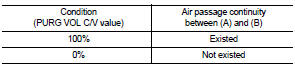
6. Touch “Qd” and “Qu” on CONSULT-III screen to adjust “PURG VOL C/V” opening and check air passage continuity of EVAP canister purge volume control solenoid valve as per the following conditions.
 Without CONSULT-III
1. Turn ignition switch OFF.
2. Disconnect EVAP canister purge volume control solenoid valve harness connector.
3. Disconnect EVAP purge hoses connected to EVAP canister purge volume control solenoid valve.
4. Check air passage continuity of EVAP canister purge volume control solenoid valve as per the following conditions.

YES >> INSPECTION END
NO >> Replace EVAP canister purge volume control solenoid valve. Refer to EM-28, "Exploded View".
 P0420 three way catalyst function
DTC Logic
DTC DETECTION LOGIC
The ECM monitors the switching frequency ratio of air fuel ratio (A/F)
sensor 1 and heated oxygen sensor 2.
A three way catalyst (manifold) with high oxygen storage ...
 P0500 VSS
Description
ECM receives vehicle speed signals from two different paths via CAN
communication line: One is from the
ABS actuator and electric unit (control unit) via the combination unit and the
...
Other materials:
Luggage room lamp circuit
Description
Controls the luggage room lamp (ground side) to turn the luggage room lamp ON
and OFF.
Diagnosis Procedure
CAUTION:
Before performing the diagnosis, check that the following are normal.
• Interior room lamp power supply
• Luggage room lamp bulb
1.CHECK LUGGAGE ROOM LAMP OU ...
P0102, P0103 MAF SENSOR
DTC Logic
DTC DETECTION LOGIC
DTC CONFIRMATION PROCEDURE
1.PRECONDITIONING
If DTC Confirmation Procedure has been previously conducted, always turn
ignition switch OFF and wait at
least 10 seconds before conducting the next test.
Which DTC is detected?
P0102 >> GO TO 2.
P0103 & ...
P0403 EGR volume control valve
DTC Logic
DTC DETECTION LOGIC
Diagnosis Procedure
1.CHECK EGR VOLUME CONTROL VALVE CONTROL CIRCUIT
1. Turn ignition switch OFF.
2. Disconnect EGR volume control valve harness connector and ECM harness
connector.
3. Check the continuity between EGR volume control valve terminal harness
co ...
