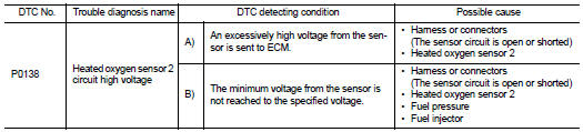
Nissan Juke Service and Repair Manual : P0138 HO2S2
DTC Logic
DTC DETECTION LOGIC
The heated oxygen sensor 2 has a much longer switching time between rich and lean than the air fuel ratio (A/ F) sensor 1. The oxygen storage capacity of the three way catalyst 1 causes the longer switching time.
MALFUNCTION A
To judge the malfunctions of heated oxygen sensor 2, ECM monitors whether the voltage is unusually high during various driving conditions such as fuel cut.
MALFUNCTION B
To judge the malfunctions of heated oxygen sensor 2, ECM monitors whether the minimum voltage of sensor is sufficiently low during various driving conditions such as fuel cut.
DTC CONFIRMATION PROCEDURE
1.PRECONDITIONING OF DTC CONFIRMATION PROCEDURE FOR MALFUNCTION A
If DTC Confirmation Procedure has been previously conducted, always turn ignition switch OFF and wait at least 10 seconds before conducting the next test.
>> GO TO 2.
2.PERFORM DTC CONFIRMATION PROCEDURE FOR MALFUNCTION A
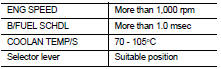
1. Start engine and warm it up to the normal operating temperature.
2. Turn ignition switch OFF and wait at least 10 seconds.
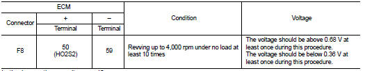
3. Restart engine and keep the engine speed between 3,500 and 4,000 rpm for at least 1 minute under no load.
4. Check 1st trip DTC.
Is 1st trip DTC detected? YES >> Go to EC-624, "Diagnosis Procedure".
NO-1 >> With CONSULT-III: GO TO 3.
NO-2 >> Without CONSULT-III: GO TO 12.
3.PRECONDITIONING OF DTC CONFIRMATION PROCEDURE FOR MALFUNCTION B
“COMPLETED” will appear on CONSULT-III screen when all tests “COND1”, “COND2” and “COND3” are completed.
TESTING CONDITION:
• For the best results, perform “DTC WORK SUPPORT” at a temperature of 0 to 30
°C (32 to 86 °F).
• Never stop engine during this procedure. If the engine is stopped, retry procedure from PERFORM PROCEDURE FOR COND1-II.
>> GO TO 4.
4.PERFORM PROCEDURE FOR COND1-I
Start engine and warm it up to the normal operating temperature.
>> GO TO 5.
5.PERFORM PROCEDURE FOR COND1-II
Turn ignition switch OFF and wait at least 10 seconds.
>> GO TO 6.
6.PERFORM PROCEDURE FOR COND1-III
1. Start engine and keep the engine speed between 3,500 and 4,000 rpm for at least 1 minute under no load.
2. Let engine idle for 1 minute.
3. Select “ENGINE” using CONSULT-III.
4. Select “HO2S2 (B1) P1146” of “HO2S2” in “DTC WORK SUPPORT” mode.
5. Touch “START”.
6. Let engine idle for at least 30 seconds.
7. Rev engine up to 2,000 rpm two or three times quickly under no load.
Is “COMPLETED” appears on CONSULT-III screen? YES >> GO TO 8.
NO >> GO TO 7.
7.PERFORM PROCEDURE FOR COND1-IV
When the following conditions are met, “TESTING” will be displayed at “COND1” on the CONSULT-III screen.
Maintain the conditions continuously until “TESTING” changes to “COMPLETED”
CAUTION:
Always drive vehicle at a safe spee
d.
Which displayed on CONSULT-III screen? “COND1: OUT OF CONDITION”>>GO TO 5.
“COND1: COMPLETED”, “COND2: INCOMPLETE”>>GO TO 8.
“COND1: COMPLETED”, “COND2: COMPLETED”>>GO TO 9.
8.PERFORM PROCEDURE FOR COND2
While driving, release accelerator pedal completed from the above condition (PERFORM PROCEDURE FOR COND1-III) until “INCOMPLETE” at “COND2” on CONSULT-III screen has turned to “COMPLETED” (It will take approximately 4 seconds).
CAUTION:
Always drive vehicle at a safe speed.
Which displayed on CONSULT-III screen? “COND2: COMPLETED”, “COND3: INCOMPLETE”>>GO TO 9.
“COND2: COMPLETED”, “COND3: COMPLETED”>>GO TO 10.
9.PERFORM PROCEDURE FOR COND3-I
Stop vehicle and let it idle until “INCOMPLETE” of “COND3” on CONSULT-III screen has turned to “COMPLETED” >> GO TO 10.
10.PERFORM PROCEDURE FOR COND3-II
Touch SELF-DIAG RESULTS”.
Which displayed on CONSULT-III screen? “OK” >> INSPECTION END.
“NG” >> Go to EC-624, "Diagnosis Procedure".
“CAN NOT BE DIAGNOSED”>>GO TO 11.
11.PERFORM PROCEDURE FOR COND3-III
1. Turn ignition switch OFF and leave the vehicle in a cool place (soak the vehicle).
2. Turn ignition switch ON and select ENGINE using CONSULT-III.
3. Select “COOLAN TEMP/S” in “DATA MONITOR” mode with CONSULT-III 4. Start engine and warm it up while monitoring “COOLAN TEMP/S” indication on CONSULT-III.
5. When “COOLAN TEMP/S” indication reaches 70°C (158°F).
>> GO TO 6.
12.PERFORM COMPONENT FUNCTION CHECK
Perform component function check. Refer to EC-623, "Component Function Check".
NOTE
:
Use component function check the overall function of the heated oxygen sensor 2
circuit. During this
check, a 1st trip DTC might not be confirmed.
Is the inspection result normal? YES >> INSPECTION END.
NO >> Go to EC-624, "Diagnosis Procedure".
Component Function Check
1.PERFORM COMPONENT FUNCTION CHECK-I
 Without CONSULT-III
1. Start engine and warm it up to the normal operating temperature.
2. Turn ignition switch OFF and wait at least 10 seconds.
3. Turn ignition switch ON.
4. Turn ignition switch OFF and wait at least 10 seconds.
5. Start engine and keep the engine speed between 3,500 and 4,000 rpm for at least 1 minute under no load.
6. Let engine idle for 1 minute.
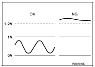
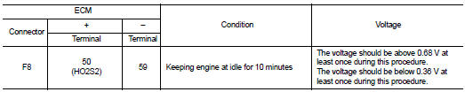
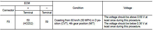
7. Check the voltage between ECM harness connector terminals under the following condition.
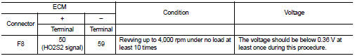
Is the inspection result normal? YES >> INSPECTION END
NO >> GO TO 2.
2.PERFORM COMPONENT FUNCTION CHECK-II
Check the voltage between ECM harness connector terminals under the following condition.
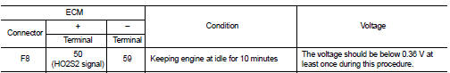
Is the inspection result normal? YES >> INSPECTION END NO >> GO TO 3.
3.PERFORM COMPONENT FUNCTION CHECK-III
Check the voltage between ECM harness connector terminals under the following condition.
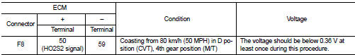
Is the inspection result normal? YES >> INSPECTION END
NO >> Go to EC-624, "Diagnosis Procedure".
Diagnosis Procedure
1.INSPECTION START
Confirm the detected malfunction (A or B). Refer to EC-621, "DTC Logic".
Which malfunction is detected? A >>GO TO 2.
B >>GO TO 9.
2.CHECK GROUND CONNECTION
1. Turn ignition switch OFF.
2. Check ground connection E21 and E38. Refer to Ground Inspection in GI-44, "Circuit Inspection".
Is the inspection result normal? YES >> GO TO 3.
NO >> Repair or replace ground connection.
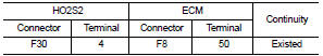
3.CHECK HO2S2 GROUND CIRCUIT FOR OPEN AND SHORT
1. Disconnect heated oxygen sensor 2 harness connector.
2. Disconnect ECM harness connector.
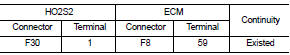
3. Check the continuity between HO2S2 harness connector and ECM harness connector.
4. Also check harness for short to ground and short to power.
Is the inspection result normal? YES >> GO TO 4.
NO >> Repair open circuit, short to ground or short to power in harness or connectors.
4.CHECK HO2S2 INPUT SIGNAL CIRCUIT FOR OPEN AND SHORT
1. Check the continuity between HO2S2 harness connector and ECM harness connector.
2. Check the continuity between HO2S2 harness connector and ground or ECM harness connector and ground.
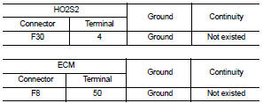
3. Also check harness for short to power.
Is the inspection result normal? YES >> GO TO 5.
NO >> Repair open circuit, short to ground or short to power in harness or connectors.
5.CHECK HO2S2 CONNECTOR FOR WATER
Check connectors for water.
Water should not exist.
Is the inspection result normal? YES >> GO TO 6.
NO >> Repair or replace harness or connectors.
6.CHECK HEATED OXYGEN SENSOR 2
Refer to EC-627, "Component Inspection".
Is the inspection result normal? YES >> GO TO 8.
NO >> GO TO 7.
7.REPLACE HEATED OXYGEN SENSOR 2
Replace malfunctioning heated oxygen sensor 2.
CAUTION:
• Discard any heated oxygen sensor which has been dropped from a height of more
than 0.5 m (19.7
in) onto a hard surface such as a concrete floor; use a new one.
• Before installing new oxygen sensor, clean exhaust system threads using Oxygen Sensor Thread Cleaner (commercial service tool) and approved anti-seize lubricant (commercial service tool
).
>> INSPECTION END
8.CHECK INTERMITTENT INCIDENT
Refer to GI-42, "Intermittent Incident".
>> INSPECTION END
9.CHECK GROUND CONNECTION
1. Turn ignition switch OFF.
2. Check ground connection E21 and E38. Refer to Ground Inspection in GI-44, "Circuit Inspection".
Is the inspection result normal? YES >> GO TO 10.
NO >> Repair or replace ground connection.
10.CLEAR THE MIXTURE RATIO SELF-LEARNING VALUE
1. Clear the mixture ratio self-learning value. Refer to EC-546, "Work Procedure".
2. Run engine for at least 10 minutes at idle speed.
Is the 1st trip DTC P0172 detected? Is it difficult to start engine? YES >> Perform trouble diagnosis for DTC P0172. Refer to EC-639, "DTC Logic".
NO >> GO TO 11.
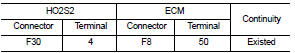
11.CHECK HO2S2 GROUND CIRCUIT FOR OPEN AND SHORT
1. Turn ignition switch OFF.
2. Disconnect heated oxygen sensor 2 harness connector.
3. Disconnect ECM harness connector.
4. Check the continuity between HO2S2 harness connector and ECM harness connector.

5. Also check harness for short to ground and short to power.
Is the inspection result normal? YES >> GO TO 12.
NO >> Repair open circuit or short to ground or short to power in harness or connectors.
12.CHECK HO2S2 INPUT SIGNAL CIRCUIT FOR OPEN AND SHORT
1. Check the continuity between HO2S2 harness connector and ECM harness connector.
2. Check the continuity between HO2S2 harness connector or ECM harness connector and ground.
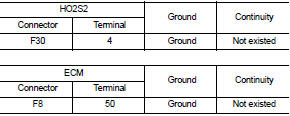
3. Also check harness for short to power.
Is the inspection result normal? YES >> GO TO 13.
NO >> Repair open circuit, short to ground or short to power in harness or connectors.
13.CHECK HEATED OXYGEN SENSOR 2
Refer to EC-627, "Component Inspection".
Is the inspection result normal? YES >> GO TO 15.
NO >> GO TO 14.
14.REPLACE HEATED OXYGEN SENSOR 2
Replace malfunctioning heated oxygen sensor 2.
CAUTION:
• Discard any heated oxygen sensor which has been dropped from a height of more
than 0.5 m (19.7
in) onto a hard surface such as a concrete floor; use a new one.
• Before installing new oxygen sensor, clean exhaust system threads using Oxygen Sensor Thread Cleaner (commercial service tool) and approved anti-seize lubricant (commercial service tool).
>> INSPECTION END
15.CHECK INTERMITTENT INCIDENT
Refer to GI-42, "Intermittent Incident".
>> INSPECTION END
Component Inspection
1.INSPECTION START
Do you have CONSULT-III? Do you have CONSULT-III? YES >> GO TO 2.
NO >> GO TO 3.
2.CHECK HEATED OXYGEN SENSOR 2
 With CONSULT-III
1. Turn ignition switch ON and select “ENGINE” using CONSULT-III.
2. Select “DATA MONITOR” mode.
3. Start engine and warm it up to the normal operating temperature.
4. Turn ignition switch OFF and wait at least 10 seconds.
5. Start engine and keep the engine speed between 3,500 and 4,000 rpm for at least 1 minute under no load.
6. Let engine idle for 1 minute.
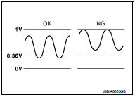
7. Select “FUEL INJECTION” in “ACTIVE TEST” mode, and select “HO2S2 (B1)” as the monitor item with CONSULT-III.
8. Check “HO2S2 (B1)” at idle speed when adjusting “FUEL INJECTION” to ±25%.
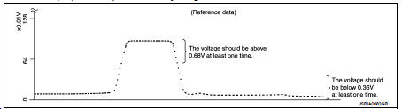
“HO2S2 (B1)” should be above 0.68 V at least once when the “FUEL INJECTION” is +25%.
‚ÄúHO2S2 (B1)‚Äù should be below 0.36 V at least once when the ‚ÄúFUEL INJECTION‚Äù is −25%
.
Is the inspection result normal? YES >> INSPECTION END
NO >> GO TO 6.
3.CHECK HEATED OXYGEN SENSOR 2-I
 Without CONSULT-III
1. Start engine and warm it up to the normal operating temperature.
2. Turn ignition switch OFF and wait at least 10 seconds.
3. Start engine and keep the engine speed between 3,500 and 4,000 rpm for at least 1 minute under no load.
4. Let engine idle for 1 minute.
5. Check the voltage between ECM harness connector terminals under the following condition.
Is the inspection result normal? YES >> INSPECTION END
NO >> GO TO 4.
4.CHECK HEATED OXYGEN SENSOR 2-II
Check the voltage between ECM harness connector terminals under the following condition.
Is the inspection result normal? YES >> INSPECTION END
NO >> GO TO 5.
5.CHECK HEATED OXYGEN SENSOR 2-III
Check the voltage between ECM harness connector terminals under the following condition.
Is the inspection result normal? YES >> INSPECTION END
NO >> GO TO 6.
6.REPLACE HEATED OXYGEN SENSOR 2
Replace malfunctioning heated oxygen sensor 2.
CAUTION:
• Discard any heated oxygen sensor which has been dropped from a height of more
than 0.5 m (19.7
in) onto a hard surface such as a concrete floor; use a new one.
• Before installing new oxygen sensor, clean exhaust system threads using Oxygen Sensor Thread Cleaner (commercial service tool) and approved anti-seize lubricant (commercial service tool).
>> INSPECTION END
 P0137 HO2S2
DTC Logic
DTC DETECTION LOGIC
The heated oxygen sensor 2 has a much longer switching time
between rich and lean than the air fuel ratio (A/F) sensor 1. The oxygen
storage capacity of the three way ...
 P0139 HO2S2
DTC Logic
DTC DETECTION LOGIC
The heated oxygen sensor 2 has a much longer switching time
between rich and lean than the air fuel ratio (A/F) sensor 1. The oxygen
storage capacity of the three way ...
Other materials:
NISSAN Advanced Air Bag System (front seats)
1. Crash zone sensor
2. Supplemental front-impact air bag modules
3. Front seat-mounted side-impact supplemental air bag modules
4. Occupant classification sensors (weight sensors)
5. Occupant classification system control unit
6. Roof-mounted curtain side-impact supplemental air bag inflator ...
Door does not lock/unlock with keyfob
Diagnosis Procedure
1.CHECK POWER DOOR LOCK OPERATION
Check power door lock operation.
Does door lock/unlock with door lock and unlock switch?
YES >> GO TO 2.
NO >> Go to DLK-534, "ALL DOOR : Diagnosis Procedure".
2.CHECK REMOTE KEYLESS ENTRY RECEIVER
Check remote ...
Drive belt
Exploded View
1. Alternator
2. Drive belt auto-tensioner
3. Crankshaft pulley
4. A/C compressor
5. Water pump
6. Drive belt
A. Possible use range
B.
Range when new drive belt is installed
C. Indicator
Checking
WARNING:
Perform this step when engine is stopped.
• Check that ...
