Nissan Juke Service and Repair Manual : P0011 IVT control
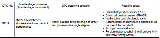
DTC Logic
DTC DETECTION LOGIC
NOTE:
If DTC P0011 is displayed with DTC P0075, first perform the trouble diagnosis
for EC-307, "DTC Logic".
DTC CONFIRMATION PROCEDURE
1.PRECONDITIONING
If DTC Confirmation Procedure has been previously conducted, always perform the following procedure before conducting the next test.
1. Turn ignition switch OFF and wait at least 10 seconds.
2. Turn ignition switch ON.
3. Turn ignition switch OFF and wait at least 10 seconds.
TESTING CONDITION:
Before performing the following procedure, confirm that battery voltage is
between 10 V and 16 V at
idle.
>> GO TO 2.
2.PERFORM DTC CONFIRMATION PROCEDURE-I
 With CONSULT-III
1. Turn ignition switch ON and select ŌĆ£DATA MONITORŌĆØ mode of ŌĆ£ENGINEŌĆØ using
CONSULT-III.
2. Start engine and warm it up to normal operating temperature.
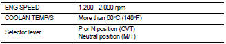
3. Maintain the following conditions for at least 6 consecutive seconds. Hold the accelerator pedal as steady as possible.
4. Stop vehicle with engine running and let engine idle for 10 seconds.
5. Check 1st trip DTC.
 With GST
Follow the procedure ŌĆ£With CONSULT-IIIŌĆØ above.
Is 1st trip DTC detected? YES >> Proceed to EC-163, "Diagnosis Procedure".
NO >> GO TO 3.
3.PERFORM DTC CONFIRMATION
3.PERFORM DTC CONFIRMATION PROCEDURE-II
With CONSULT-III
1. Maintain the following conditions for at least 20 consecutive seconds.
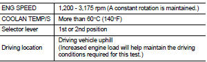
CAUTION:
Always drive at a safe speed.
2. Check 1st trip DTC.
With GST
Follow the procedure ŌĆ£With CONSULT-IIIŌĆØ above.
Is 1st trip DTC detected? YES >> Proceed to EC-163, "Diagnosis Procedure".
NO >> INSPECTION END
Diagnosis Procedure
1.CHECK OIL PRESSURE WARNING LAMP
1. Start engine.
2. Check oil pressure warning lamp and confirm it is not illuminated.
Is oil pressure warning lamp illuminated? YES >> Check the engine oil level. Refer to LU-8, "Inspection".
NO >> GO TO 2.
2.CHECK INTAKE VALVE TIMING CONTROL SOLENOID VALVE
Check the intake valve timing control solenoid valve. Refer to EC-164, "Component Inspection".
Is the inspection result normal? YES >> GO TO 3.
NO >> Replace intake valve timing control solenoid valve. Refer to EM-67, "Exploded View".
3.CHECK CRANKSHAFT POSITION SENSOR (POS)
Check the crankshaft position sensor (POS). Refer to EC-273, "Component Inspection".
Is the inspection result normal? YES >> GO TO 4.
NO >> Replace crankshaft position sensor (POS). Refer to EM-103, "Exploded View".
4.CHECK CAMSHAFT POSITION SENSOR (PHASE)
Check the camshaft position sensor (PHASE). Refer to EC-276, "Component Inspection".
Is the inspection result normal? YES >> GO TO 5.
NO >> Replace camshaft position sensor (PHASE). Refer to EM-78, "Exploded View".
5.CHECK CAMSHAFT (INT)
Check the following.
ŌĆó Accumulation of debris to the signal plate of camshaft (1) rear end ŌĆó Chipping signal plate of camshaft rear end Is the inspection result normal? YES >> GO TO 6.
NO >> Remove debris and clean the signal plate of camshaft rear end or replace camshaft. Refer to EM-79, "Removal and Installation".
6.CHECK TIMING CHAIN INSTALLATION
Check service records for any recent repairs that may cause timing chain misaligned.
Are there any service records that may cause timing chain misaligned? YES >> Check timing chain installation. Refer to EM-68, "Removal and Installation".
NO >> GO TO 7.
7.CHECK LUBRICATION CIRCUIT
Refer to LU-8, "Inspection", ŌĆ£INSPECTION AFTER INSTALLATIONŌĆØ.
Is the inspection result normal? YES >> Check intermittent incident. Refer to GI-42, "Intermittent Incident".
NO >> Clean lubrication line.
Component Inspection
1.CHECK INTAKE VALVE TIMING CONTROL SOLENOID VALVE-I
1. Turn ignition switch OFF.
2. Disconnect intake valve timing control solenoid valve harness connector.
3. Check resistance between intake valve timing control solenoid valve terminals as per the following.
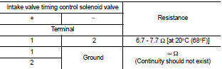
Is the inspection result normal? YES >> GO TO 2.
NO >> Replace intake valve timing control solenoid valve. Refer to EM-67, "Exploded View".
2.CHECK INTAKE VALVE TIMING CONTROL SOLENOID VALVE-II
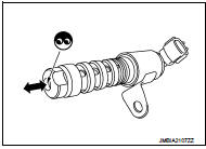
1. Remove intake valve timing control solenoid valve. Refer to EM-67, "Exploded View".
2. Provide 12 V DC between intake valve timing control solenoid valve terminals 1 and 2, and then interrupt it. Make sure that the plunger moves as shown in the figure.
CAUTION:
Do not apply 12 V DC continuously for 5 seconds or more.
Doing so may result in damage to the coil in intake valve timing control solenoid valve.
NOTE
:
Always replace O-ring when intake valve timing control
solenoid valve is removed.
Is the inspection result normal? YES >> INSPECTION END NO >> Replace intake valve timing control solenoid valve. Refer to EM-67, "Exploded View".
 U1001 Can comm circuit
Description
CAN (Controller Area Network) is a serial communication line for real time
application. It is an on-vehicle multiplex
communication line with high data communication speed and excelle ...
 P0014 EVT control
DTC Logic
DTC DETECTION LOGIC
NOTE:
ŌĆó If DTC P0014 is displayed with DTC P0078, first perform trouble diagnosis for
DTC P0078. Refer to
EC-179, "DTC Logic".
ŌĆó If DTC P0014 is disp ...
Other materials:
Mixture ratio self-learning value
clear
Description
This describes how to erase the mixture ratio self-learning value. For the
actual procedure, follow the instructions
in ŌĆ£Diagnosis ProcedureŌĆØ.
Work Procedure
With CONSULT-III
1. Start engine and warm it up to normal operating temperature.
2. Select ŌĆ£SELF-LEARNING CONTŌĆØ in ...
5TH injector
Exploded View
1. 5th injector retaining bracket
2. 5th injector bolt
3. 5th injector
4. Injector seal
5. Diesel injector cooler
6. Gasket
7. Turbocharger outlet duct
: N┬Ęm (kg-m, ft-lb)
: Always replace after every
disassembly.
Removal and Installation
REMOVAL
CAUTION:
ŌĆó Be s ...
Wiring diagram
METER SYSTEM
Wiring Diagram
For connector terminal arrangements, harness layouts, and alphabets in a
(option abbreviation; if not
described in wiring diagram), refer to GI-12, "Connector Information/Explanation
of Option Abbreviation".
...
