Nissan Juke Service and Repair Manual : Oil seal
Valve oil seal
VALVE OIL SEAL : Removal and Installation
REMOVAL
1. Remove camshafts. Refer to EM-191, "Exploded View".
2. Remove valve lifters. Refer to EM-191, "Exploded View".
3. Rotate crankshaft, and set piston whose valve oil seal is to be removed to TDC. This will prevent valve from dropping into cylinder.
CAUTION:
When rotating crankshaft, be careful to avoid scarring front cover with timing
chain.
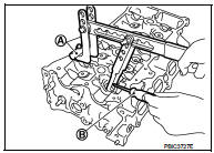
4. Remove valve collet.
• Compress valve spring with the valve spring compressor [SST: KV10116200] (A), the attachment [SST: KV10115900] (C), and the adapter [SST: KV10109220] (B). Remove valve collet with magnet hand.
CAUTION:
Be careful not to damage valve lifter holes.
5. Remove valve spring retainer and valve spring (with valve spring seat).
CAUTION:
Never remove valve spring seat from valve spring.
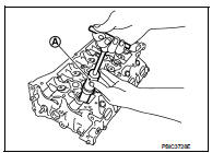
6. Remove valve oil seal with the valve oil seal puller [SST: KV10107902] (A).
INSTALLATION
1. Apply new engine oil to valve oil seal joint surface and seal lip.
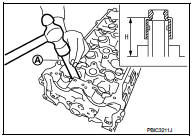
2. Press in valve oil seal to the height (H) shown in the figure with the valve oil seal drift [SST: KV10115600] (A).
Height (H) : 13.2 - 13.8 mm (0.520 - 0.543 in)
3. Install in the reverse order of removal, for the rest of parts.
Front oil seal
FRONT OIL SEAL : Removal and Installation
REMOVAL
1. Remove the following parts.
• Remove fillet mold : Refer to EXT-26, "Exploded View" • Front fender protector (RH): Refer to EXT-22, "Exploded View".
• Drive belt: Refer to EM-155, "Removal and Installation".
• Crankshaft pulley: Refer to EM-181, "Exploded View".
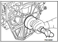
2. Remove front oil seal with a suitable tool.
CAUTION:
Be careful not to damage front cover and crankshaft
.
INSTALLATION
1. Apply new engine oil to new front oil seal joint surface and seal lip.
2. Install front oil seal so that each seal lip is oriented as shown in the figure.
A : Dust seal lip
B : Oil seal lip
 : Engine outside
 : Engine inside
• Press-fit front oil seal using a suitable drift with outer diameter 50 mm (1.97 in) and inner diameter 44 mm (1.73 in).
CAUTION:
• Be careful not to damage front cover and crankshaft.
• Press-fit oil seal straight to avoid causing burrs or tilting.
3. Install in the reverse order of removal, for the rest of parts.
Rear oil seal
REAR OIL SEAL : Removal and Installation
REMOVAL
1. Remove transaxle assembly. Refer to TM-30, "Exploded View" (M/T models), TM-508, "Exploded View" (CVT models).
2. Remove clutch cover and clutch disk (M/T models). Refer to CL-29, "EXCEPT FOR K9K : Exploded View".
3. Remove flywheel (M/T models) or drive plate (CVT models). Refer to EM-227, "Exploded View".
4. Remove rear oil seal with a suitable tool.
CAUTION:
Be careful not to damage crankshaft and cylinder block.
INSTALLATION
1. Apply the liquid gasket lightly to entire outside area of new rear oil seal.
Use Genuine Liquid Gasket or equivalent.
2. Install rear oil seal so that each seal lip is oriented as shown in the figure.
A : Dust seal lip
B : Oil seal lip
 : Engine outside
 : Engine inside
• Press-fit rear oil seal with a suitable drift (A) outer diameter 113 mm (4.45 in) and inner diameter 90 mm (3.54 in).
CAUTION:
• Be careful not to damage crankshaft and cylinder block.
• Press-fit oil seal straight to avoid causing burrs or tilting.
• Never touch grease applied onto oil seal lip.
• Press in rear oil seal (1) to the position as shown in the figure.
A : Rear end surface of cylinder block b : 0 - 0.5 mm (0 - 0.020 in)
3. Install in the reverse order of removal, for the rest of parts.
 Camshaft
Exploded View
1. Camshaft bracket (No. 2 to 5)
2. Camshaft bracket (No. 1)
3. Camshaft sprocket (EXH)
4.Exhaust valve timing control solenoid
valve
5. O-ring
6.Camshaft sprocket (INT)
7. ...
 Cylinder head
Exploded View
REMOVAL
1. Cylinder head assembly
2. Cylinder head bolt
3. Washer
4. Cylinder head gasket
A.Tightening must be done following the installation procedure.
Refer to EM-209
: ...
Other materials:
Flat towing
Towing your vehicle with all four wheels on the ground is sometimes called flat
towing. This method is sometimes used when towing a vehicle behind a recreational
vehicle, such as a motor home.
CAUTION
• Failure to follow these guidelines can result in severe transmission damage.
• Wheneve ...
Inside mirror
Exploded View
Manual anti-dazzling type
1. Windshield glass
2. Mirror base
3. Inside mirror assembly
: Do not reuse
Auto anti-dazzling type
1. Rain sensor bracket
2. Mirror base
3. Rain sensor
4. Inside mirror assembly
: Pawl
: Do not reuse
Removal and Installation
CAUTION:
Ne ...
Checking bulbs
With all doors closed, apply the parking brake and place the ignition switch
in the ON position without starting the engine. The following lights will come on:
,
or
,
,
,
,
,
The following lights come on briefly and then go off (if so equipped):
,
or
,
,
,
,
,
,
,
,
,
If ...
