Nissan Juke Service and Repair Manual : Magnet clutch
Component Function Check
1.CHECK MAGNET CLUTCH OPERATION
Perform auto active test of IPDM E/R. Refer to PCS-12, "Diagnosis Description" (with Intelligent Key) or PCS- 43, "Diagnosis Description" (without Intelligent Key).
Does it operate normally? YES >> INSPECTION END
NO >> Refer to HAC-232, "Diagnosis Procedure".
Diagnosis Procedure
1.CHECK FUSE
1. Turn ignition switch OFF.
2. Check 10A fuse (No. 49, located in IPDM E/R).
NOTE: Refer to PG-25, "Fuse, Connector and Terminal Arrangement".
Is the inspection result normal? YES >> GO TO 2.
NO >> Replace the blown fuse after repairing the affected circuit if a fuse is blown.
2.CHECK MAGNET CLUTCH
1. Disconnect compressor connector.
2. Directly apply battery voltage to the magnet clutch. Check for operation visually and by sound.
Does it operate normally? YES >> GO TO 3.
NO >> Replace magnet clutch. Refer to HA-88, "MAGNET CLUTCH : Removal and Installation of Compressor Clutch".
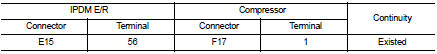
3.CHECK MAGNET CLUTCH POWER SUPPLY CIRCUIT FOR OPEN
1. Disconnect IPDM E/R connector.
2. Check continuity between IPDM E/R harness connector and compressor harness connector.
Is the inspection result normal? YES >> Replace IPDM E/R. Refer to PCS-34, "Removal and Installation" (with Intelligent Key) or PCS-63, "Removal and Installation" (without Intelligent Key).
NO >> Repair harness or connector.
 Blower motor
Diagnosis Procedure
1.CHECK SYMPTOM
Check symptom (A or B).
Which symptom is detected?
A >>GO TO 2.
B >>GO TO 7.
2.CHECK FUSE
1. Turn ignition switch OFF.
2. Check 15A fuses ...

Other materials:
P0087 fuel pump
DTC Logic
DTC DETECTION LOGIC
NOTE:
• Conditions for applying the diagnostic procedure to the stored DTCs:
The DTC becomes present during the first 30 seconds after the engine starts.
• In low ambient temperature conditions, diagnostic cannot make difference
between a normal long engine ...
B1144 diagnosis sensor unit
DTC Logic
DTC DETECTION LOGIC
DTC CONFIRMATION PROCEDURE
1.CHECK SELF-DIAG RESULT
With CONSULT-III
1. Turn ignition switch ON.
2. Perform “Self Diagnostic Result” mode of “AIR BAG” using CONSULT-III.
Without CONSULT-III
1. Turn ignition switch ON.
2. Check the air bag warning la ...
B260F Engine status
Description
BCM receives the engine status signal from ECM via CAN communication.
DTC Logic
DTC DETECTION LOGIC
NOTE:
• If DTC B260F is displayed with DTC U1000, first perform the trouble diagnosis
for DTC U1000. Refer to
BCS-83, "DTC Logic".
• If DTC B260F is displayed with D ...
