Nissan Juke Service and Repair Manual : Lubricant
Description
MAINTENANCE OF LUBRICANT LEVEL
The compressor lubricant is circulating in the system together with the refrigerant. It is necessary to fill compressor with lubricant when replacing A/C system parts or when a large amount of refrigerant leakage is detected. It is important to always maintain lubricant level within the specified level. Otherwise, the following conditions may occur.
• Insufficient lubricant amount: Stuck compressor • Excessive lubricant amount: Insufficient cooling (caused by insufficient heat exchange)
Name : A/C system Oil Type R
Inspection
If a compressor is malfunctioning (internal noise, insufficient cooling), check the compressor oil.
1.COMPRESSOR OIL JUDGMENT
1. Remove the compressor. Refer to HA-87, "COMPRESSOR : Removal and Installation".
2. Sample a compressor oil and judge on the figure.
Judgement result 1>>Replace compressor only.
Judgement result 2>>Replace compressor and liquid tank.
Perform Lubricant Return Operation
CAUTION:
If a large amount of refrigerant or lubricant leakage is detected, never perform
lubricant return operation.
1. Start the engine and set to the following conditions.
• Engine speed: Idling to 1,200 rpm
• A/C switch: ON
• Fan speed: Maximum speed set
• Intake door position: Recirculation
• Temperature setting: Full cold
2. Perform lubricant return operation for approximately 10 minutes.
3. Stop the engine.
4. Lubricant return operation is complete.
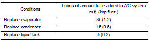
Lubricant Adjusting Procedure for Components Replacement Except Compressor
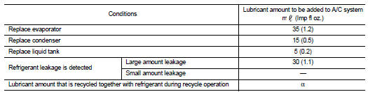
Fill with lubricant for the amount that is calculated according to the following conditions.
Example: Lubricant amount to be added when replacing evaporator and liquid tank [m (Imp fl oz.)] = 35 (1.2) + 5 (0.2) + α
Lubricant Adjusting Procedure for Compressor Replacement
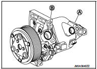
1. Drain lubricant from removed compressor and measure lubricant amount.
1. Drain lubricant from high-pressure port (A) and low-pressure port (B) while rotating magnet clutch.
2. Measure total amount of lubricant that is drained from removed compressor.
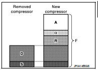
2. Drain lubricant from a new compressor that is calculated according to the following conditions.
Amount to be drained (A) [m (Imp fl oz.)] = F − (D
+ S + R + α)
F : Lubricant amount that a new compressor
contains [120 (4.2)]
D : Lubricant amount that is drained from removed
compressor
S : Lubricant amount that remains inside of removed
compressor [20 (0.7)]
R : Lubricant amount to be added according to
components that are removed except compressor
α : Lubricant amount that is recycled together
with refrigerant during recycle operation
CAUTION:
If lubricant amount that is drained from removed compressor is less than 60 m
(2.1 Imp fl oz.),
perform calculation by setting “D” as 40 m (1.4 Imp fl oz.).
Example: Lubricant amount to be drained from a new compressor when replacing compressor and liquid tank [m (Imp fl oz.)] [D = 60 (2.1), α = 5 (0.2)] 120 (4.2) − [60 (1.6) + 20 (0.7) + 5 (0.2) + 5 (0.2)] = 30 (1.0)
3. Install compressor and check the operation.
 Refrigerant
Description
CONNECTION OF SERVICE TOOLS AND EQUIPMENT
1. Shut-off valve
2. A/C service valve
3. Recovery/recycling/recharging
equipment
4. Vacuum pump
5. Manifold gauge set
6. Refrigeran ...
 Performance test
Inspection
INSPECTION PROCEDURE
1. Connect recovery/recycling/recharging equipment (for HFC-134a) or manifold
gauge.
2. Start the engine, and set to the following condition.
Test condition
...
Other materials:
Opening charge port lid
Instrument panel switch
When opening the charge port lid to plug in a charging connector, perform one of the following official interface actions:
Push the physical charge port lid switch located on the lower instrument panel to the left of the steering ...
Squeak and rattle trouble diagnoses
Work Flow
CUSTOMER INTERVIEW
Interview the customer if possible, to determine the conditions that exist
when the noise occurs. Use the Diagnostic
Worksheet during the interview to document the facts and conditions when the
noise occurs and any of
the customer's comments; refer to MIR-39, & ...
Integrated control system (if so equipped)
The Integrated Control System is located below the audio system or navigation
system (if so equipped). Two Integrated Control System modes can be selected: Drive
mode and Climate Control mode.
Depending on which Integrated Control System mode is selected (Drive mode or
Climate Control mode), ...
