Nissan Juke Service and Repair Manual : Interior room lamp power supply circuit
Description
Provides the interior room lamp power supply. Also cuts the power supply when the interior room lamp battery saver activating.
Component Function Check
1.CHECK INTERIOR ROOM LAMP POWER SUPPLY FUNCTION
 CONSULT-III ACTIVE TEST
1. Turn ignition switch ON.
2. Turn each interior room lamp ON.
- Map lamp
- Luggage room lamp
3. Select “BATTERY SAVER” of BCM (BATTERY SAVER) active test item.
4. With operating the test items, check that each interior room lamp turns ON/OFF.
Off : Interior room lamp OFF On : Interior room lamp ON
Does each interior room lamp turn ON/OFF? YES >> Interior room lamp power supply circuit is normal.
NO >> Refer to INL-28, "Diagnosis Procedure".
Diagnosis Procedure
1.CHECK INTERIOR ROOM LAMP POWER SUPPLY OUTPUT
 CONSULT-III ACTIVE TEST
1. Turn ignition switch OFF.
2. Disconnect the following connectors.
- Map lamp
- Luggage room lamp
3. Turn ignition switch ON.
4. Select “BATTERY SAVER” of BCM (BATTERY SAVER) active test item.
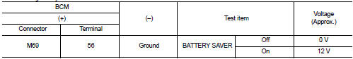
5. With operating the test item, check voltage between BCM harness connector and ground.
With Intelligent Key
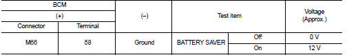
Without Intelligent Key
Is the inspection result normal? YES >> GO TO 2.
NO >> GO TO 3.
2.CHECK INTERIOR ROOM LAMP POWER SUPPLY OPEN CIRCUIT
1. Turn ignition switch OFF.
2. Disconnect the BCM connector.
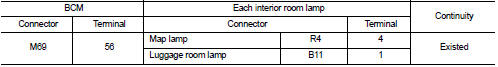
3. Check continuity between BCM harness connector and each interior room lamp harness connector.
With Intelligent Key
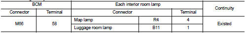
Without Intelligent Key
Is the inspection result normal? YES >> Check for internal short circuit of each interior room lamp.
NO >> Repair or replace harnesses.
3.CHECK INTERIOR ROOM LAMP POWER SUPPLY SHORT CIRCUIT
1. Turn ignition switch OFF.
2. Disconnect the BCM connector.
3. Check continuity between BCM harness connector and ground.
With Intelligent Key

Without Intelligent Key

Is the inspection result normal? YES >> Replace BCM. Refer to BCS-93, "Removal and Installation".
NO >> Repair or replace harnesses.

 Interior room lamp control circuit
Description
Controls each interior room lamp (ground side) by PWM signal.
NOTE:
PWM signal control period is approximately 250 Hz (in the gradual
brightening/dimming).
Component Function Check ...
Other materials:
Structure and operation
Transaxle : Cross-Sectional View
1. Converter housing
2. Oil pump
3. Counter drive gear
4. Control valve
5. Oil pan
6. Primary pulley
7. Steel belt
8. Secondary pulley
9. Planetary gear (auxiliary gearbox)
10. Side cover
11. Transaxle case
12. Differential case
13. Final gear ...
Removal and Installation
REMOVAL
• Disconnect each joint and mounting.
• Remove heated oxygen sensor 2 with following procedure:
- Using heated oxygen sensor wrench [SST: KV10114400] (A),
removal heated oxygen sensor 2 (1).
CAUTION:
Be careful not to damage heated oxygen sensor 2.
INSTALLATION
Note the follo ...
P position warning does not operate
Diagnosis Procedure
1.CHECK DTC WITH BCM, TCM AND COMBINATION METER
Check that DTC is not detected with BCM, TCM and combination meter.
Is the inspection result normal?
YES >> GO TO 2.
NO-1 >> Refer to BCS-67, "DTC Index". (BCM)
NO-2 >> Refer to TM-171, "DT ...
