Nissan Juke Service and Repair Manual : Hood lock
Exploded View
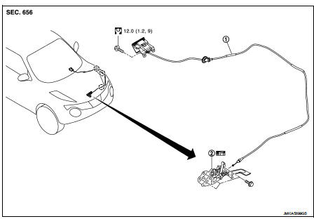
1. Hood lock control cable assembly 2. Hood lock assembly
 : Clip
 : N·m (kg-m, ft-lb)
 : Body grease
Hood lock
HOOD LOCK : Removal and Installation
REMOVAL
1. Remove front center grille. Refer to EXT-18, "Removal and Installation".
2. Remove crash zone sensor. Refer to SR-26, "Removal and Installation".
3. Remove hood lock assembly mounting bolts, and then remove hood lock assembly.
4. Disconnect hood lock control cable assembly (2) from hood lock assembly (1).
INSTALLATION
Note the following items, and install in the reverse order of removal.
CAUTION:
• Check that hood lock control cable is properly engaged with hood lock.
• After installation, perform hood fitting adjustment. Refer to DLK-305, "HOOD ASSEMBLY : Adjustment".
• After installation, perform hood lock control inspection. Refer to DLK-336, "Inspection".
Hood lock control cable
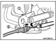
HOOD LOCK CONTROL CABLE : Removal and Installation
REMOVAL
1. Disconnect hood lock control cable assembly from hood lock assembly.
2. Remove fender protector (LH). Refer to EXT-22, "Removal and Installation".
3. Remove hood lock cable clip.
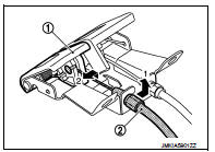
4. Remove hood lock control cable assembly of instrument lower panel (LH), and then remove fuel filler lid opener cable (2) from fuel filler lid opener lever (1).
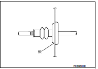
5. Remove grommet on the lower dash, and pull the hood lock control cable toward the passenger compartment.
CAUTION:
While pulling, never to damage (peeling) the outside of hood lock control ca
ble.
INSTALLATION
Note the following items, and install in the reverse order of removal.
CAUTION:
• Never to bend cable too much, keeping the radius 100 mm (3.937 in) or more.
• Check that cable is not offset from the positioning grommet, and apply the sealant to the grommet (at * mark) properly.
• Check that hood lock control cable is properly engaged with hood lock.
• After installation, perform hood fitting adjustment. Refer to DLK-305, "HOOD ASSEMBLY : Adjustment".
• After installation, perform hood lock control inspection. Refer to DLK-336, "Inspection".
Inspection
NOTE
:
If the hood lock cable is bent or deformed, replace it.
1. Check that secondary latch is securely engaged with securely striker from the dead load of the hood assembly.
2. Check that primary latch is securely engaged with primary striker when hood assembly is closed [free-fall from approximately 200 mm (7.874 in) height].
CAUTION:
Never free-fall hood assembly from a height of 300 (11.811 in) mm or more.
3. While operating the hood opener carefully, check that the front end of the hood is lifted by approximately 20 mm (0.787 in) (A). Also, check that the hood opener returns to the original position.
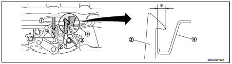
1. Primary striker
2. Primary latch
3. Secondary latch
4. Secondary striker
4. Check that secondary latch is properly engaged with secondary striker [6.8 mm (0.268 in)] (B).
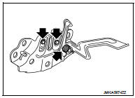
5. Check the hood lock lubrication condition. If necessary, apply body grease to hood lock.
 : Grease up point
 Back door
Exploded View
REMOVAL
1. Back door weather-strip
2. Back door stay
3. Back door stay lower bracket
4. Bumper rubber
5. Back door striker
6. Back door panel
7. Back door hinge
8. Hole c ...
 Front door lock
Exploded View
1. Door key cylinder assembly (driver
side)
Outside handle escutcheon (passenger
side)
2. Rear gasket
3. Outside handle bracket
4. TORX bolt
5. Key rod (driver side)
6. Doo ...
Other materials:
Too much power
Description
CHART 13: TOO MUCH POWER
Diagnosis Procedure
1.CHECK ECM POWER SUPPLY AND GROUND CIRCUIT
Check ECM power supply and ground circuit. Refer to EC-885, "Diagnosis
Procedure".
Is the inspection result normal?
YES >> GO TO 2.
NO >> Repair or replace harness ...
Back door does not opened
Diagnosis Procedure
1.CHECK BACK DOOR OPENER SWITCH
Check back door opener switch.
Refer to DLK-384, "Component Function Check".
Is the inspection result normal?
YES >> GO TO 2.
NO >> Repair or replace the malfunctioning parts.
2.CHECK BACK DOOR OPENER ACTUATOR
...
P0138 HO2S2
DTC Logic
DTC DETECTION LOGIC
The heated oxygen sensor 2 has a much longer switching time between rich and
lean than the air fuel ratio (A/
F) sensor 1. The oxygen storage capacity of the three way catalyst 1 causes the
longer switching time.
MALFUNCTION A
To judge the malfunctions of hea ...
