Nissan Juke Service and Repair Manual : G sensor
Exploded View
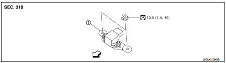
1. G sensor
 : Vehicle front
 : N·m (kg-m, in-lb)
Removal and Installation
CAUTION:
• Never drop or strike G sensor, because it has little tolerance for impact.
• Never use a power tool to avoid impact.
REMOVAL
1. Disconnect the battery cable from the negative terminal. Refer to PG-124, "Removal and Installation".
2. Remove driver seat (LHD) or passenger seat (RHD). Refer to SE-19, "Removal and Installation".
3. Remove center pillar lower garnish (left side) and dash side finisher (left side). Refer to INT-20, "CENTER PILLAR LOWER GARNISH : Removal and Installation" (center pillar lower garnish) and INT-20, "DASH SIDE FINISHER : Removal and Installation" (dash side finisher).
4. Pull up floor carpet. Refer to INT-23, "Removal and Installation".
5. Disconnect G sensor harness connector.
6. Remove G sensor.
7. Remove bracket.
INSTALLATION
Installation is the reverse order of removal.
Adjustment
ADJUSTMENT AFTER INSTALLATION
Perform “G SENSOR CALIBRATION”. Refer to TM-377, "Description".
 Air breather hose
Removal and Installation
REMOVAL
1. Remove air cleaner case. Refer to EM-26, "Removal and Installation".
2. Remove clip from bracket.
3. Remove air breather hose from transaxle assembly. ...
 Control valve
Exploded View
COMPONENT PARTS LOCATION
1. Transaxle assembly
2. Control valve
3. Bracket
4. O-ring
5. Oil strainer assembly
6. Magnet
7. Drain plug gasket
8. Drain plug
9. Oil pan mo ...
Other materials:
Fuel tank
Exploded View
1. Fuel tank cap
2. Grommet
3. Fuel filler tube
4. Clamp
5. Fuel filler hose
6. Clamp
7. Vent hose
8. Fuel tank
9. Mounting band (RH)
10. Mounting band (LH)
: N·m (kg-m, ft-lb)
Removal and Installation
WARNING:
Be sure to read “General Precautions” when worki ...
P1865 gear ratio signal
DTC Logic
DTC DETECTION LOGIC
DTC CONFIRMATION PROCEDURE
1.PRECONDITIONING
If “DTC CONFIRMATION PROCEDURE” has been previously conducted, always turn
ignition switch OFF and
wait at least 10 seconds before conducting the next test.
>> GO TO 2.
2.DTC REPRODUCTION PROCEDURE
W ...
P position warning does not operate
Diagnosis Procedure
1.CHECK DTC WITH BCM, TCM AND COMBINATION METER
Check that DTC is not detected with BCM, TCM and combination meter.
Is the inspection result normal?
YES >> GO TO 2.
NO-1 >> Refer to BCS-67, "DTC Index". (BCM)
NO-2 >> Refer to TM-171, "DT ...
