Nissan Juke Service and Repair Manual : Fuel pressure check
Work Procedure
FUEL PRESSURE RELEASE
1.FUEL PRESSURE RELEASE
 With CONSULT-III
1. Turn ignition switch ON.
2. Perform “FUEL PRESSURE RELEASE” in “WORK SUPPORT” mode with CONSULT-III.
3. Start engine.
4. After engine stalls, crank it two or three times to release all fuel pressure.
5. Turn ignition switch OFF.
 Without CONSULT-III
1. Remove fuel pump fuse located in IPDM E/R.
2. Start engine.
3. After engine stalls, crank it two or three times to release all fuel pressure.
4. Turn ignition switch OFF.
5. Reinstall fuel pump fuse after servicing fuel system.
>> INSPECTION END
FUEL PRESSURE CHECK
1.FUEL PRESSURE CHECK
CAUTION:
• Before disconnecting fuel line, release fuel pressure from fuel line to
eliminate danger.
• The fuel hose connection method used when taking fuel pressure check must not be used for other purposes.
• Be careful not to scratch or put debris around connection area when servicing, so that the quick connector maintains seal ability with O-rings inside.
• Do not perform fuel pressure check with electrical systems operating (i.e. lights, rear defogger, A/C, etc.) Fuel pressure gauge may indicate false readings due to varying engine load and changes in manifold vacuum.
NOTE:
Prepare pans or saucers under the disconnected fuel line because the fuel may spill out. The fuel pressure cannot be completely released because F15 models do not have fuel return system.
1. Release fuel pressure to zero.
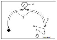
2. Prepare fuel hose for fuel pressure check (B) and fuel tube adapter [SST (KV10118400) or (KV10120000)] (D), then connect fuel pressure gauge (A).
 To quick
connector
 To fuel
tube (engine side)
C : Hose clamp
CAUTION:
• Use suitable fuel hose for fuel pressure check (genuine
NISSAN fuel hose without quick connector).
• To avoid unnecessary force or tension to hose, use moderately long fuel hose for fuel pressure check.
• Do not use the fuel hose for checking fuel pressure with damage or cracks on it.
• Use Pressure Gauge to check fuel pressure.
3. Remove fuel hose.
CAUTION:
Do not twist or kink fuel hose because it is plastic hose.
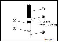
4. Connect fuel hose for fuel pressure check (1) to fuel tube (engine side) with clamp (2) as shown in the figure.
5 : No.2 spool
CAUTION:
• Wipe off oil or dirt from hose insertion part using cloth
moistened with gasoline.
• Apply proper amount of gasoline between top of the fuel tube (3) and No.1 spool (4).
• Insert fuel hose for fuel pressure check until it touches the No.1 spool on fuel tube.
• Use NISSAN genuine hose clamp (part number: 16439 N4710 or 16439 40U00).
• When reconnecting fuel line, always use new clamps.
• Use a torque driver to tighten clamps.
• Install hose clamp to the position within 1 - 2 mm (0.04 - 0.08 in).
Tightening torque : 1 - 1.5 N·m (0.1 - 0.15 kg-m, 9 - 13 in-lb)
• Make sure that clamp screw does not contact adjacent parts.
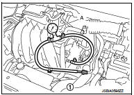
5. Connect fuel tube adapter to quick connector (1).
A : Fuel pressure gauge
6. After connecting fuel hose for fuel pressure check, pull the hose with a force of approximately 98 N (10 kg, 22 lb) to confirm fuel tube does not come off.
7. Turn ignition switch ON and check for fuel leakage.
8. Start engine and check for fuel leakage.
9. Read the indication of fuel pressure gauge.
CAUTION:
• Do not perform fuel pressure check with system operating.
Fuel pressure gauge may indicate false readings.
• During fuel pressure check, confirm for fuel leakage from fuel connection every 3 minutes.
At idling : Approximately 350 kPa (3.5 bar, 3.57 kg/cm2, 51 psi)
Is the inspection result normal? YES >> INSPECTION END
NO >> GO TO 2.
2.CHECK FUEL HOSE AND FUEL TUBE
If result is unsatisfactory, check fuel hoses and fuel tubes for clogging.
Is the inspection result normal? YES >> Replace “fuel filter and fuel pump assembly”.
NO >> Repair or replace.
 Basic inspection
Work Procedure
1.INSPECTION START
1. Check service records for any recent repairs that may indicate a related
malfunction, or a current need for
scheduled maintenance.
2. Open engine hood and ch ...
 How to set SRT code
Description
OUTLINE
In order to set all SRTs, the self-diagnoses as in the “SRT ITEM” table must
have been performed at least
once. Each diagnosis may require actual driving for a long period ...
Other materials:
P0847 transmission fluid pressure SEN/SW B
DTC Logic
DTC DETECTION LOGIC
DTC CONFIRMATION PROCEDURE
1.PREPARATION BEFORE WORK
If another "DTC CONFIRMATION PROCEDURE" occurs just before, turn ignition
switch OFF and wait for at
least 10 seconds, then perform the next test.
>> GO TO 2.
2.CHECK DTC DETECTION
With ...
e-Pedal system
WARNING
Never rely solely on the innovative e-Pedal system to manage your speed or bring the vehicle to a halt, as there is a clear physical performance limit to the system's automated deceleration functions. Always drive carefully, maintain full situational awareness, and remain highly attenti ...
P17B5 low brake solenoid
DTC Logic
DTC DETECTION LOGIC
DTC CONFIRMATION PROCEDURE
1.PREPARATION BEFORE WORK
If another "DTC CONFIRMATION PROCEDURE" occurs just before, turn ignition
switch OFF and wait for at
least 10 seconds, then perform the next test.
>> GO TO 2.
2.CHECK DTC DETECTION
1. S ...
