Nissan Juke Service and Repair Manual : Front wheel hub and knuckle
Exploded View
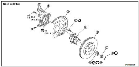
1. Steering knuckle
2. Splash guard
3. Hub bolt
4. Wheel hub assembly (Bearing-integrated
type)
5. Disc rotor
6. Wheel hub lock nut
7. Adjusting cap
8. Cotter pin
A. Tightening must be done following the installation procedure. Refer to FAX-11, "Removal and Installation".
 : Always replace after every
disassembly.
 : N·m (kg-m, ft-lb)
Removal and Installation
REMOVAL
1. Remove tires. Refer toWT-7, "Removal and Installation".
2. Remove wheel sensor and sensor harness. Refer to BRC-84, "FRONT WHEEL SENSOR : Exploded View" (Without ESP) or BRC-224, "FRONT WHEEL SENSOR : Exploded View" (With ESP).
3. Remove lock plate from strut assembly. Refer to FSU-14, "Removal and Installation".
4. Remove caliper assembly. Hang caliper assembly not to interfere with work. Refer to BR-57, "BRAKE CALIPER ASSEMBLY : Removal and Installation" (LHD) or BR-123, "BRAKE CALIPER ASSEMBLY : Removal and Installation" (RHD).
CAUTION:
Never depress brake pedal while brake caliper is removed.
5. Remove disc rotor.
CAUTION:
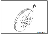
• Put matching marks (A) on the wheel hub assembly and
the disc rotor before removing the disc rotor.
• Never drop disc rotor.
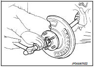
6. Remove cotter pin, and adjusting cap, and then loosen wheel hub lock nut, using a hub lock nut wrench (A) (SST: KV40104000).
7. Patch wheel hub lock nut with a piece of wood. Hammer the wood to disengage wheel hub assembly from drive shaft.
CAUTION:
• Never place drive shaft joint at an extreme angle. Also be
careful not to overextend slide joint.
• Never allow drive shaft to hang down without support for joint sub-assembly, shaft and the other parts.
NOTE:
Use suitable puller, if wheel hub assembly and drive shaft cannot be separated even after performing the above procedure.
8. Remove wheel hub lock nut.
9. Remove steering outer socket from steering knuckle. Refer to ST-19, "Removal and Installation".
10. Remove strut assembly from steering knuckle. Refer to FSU-10, "Removal and Installation".
11. Suspend the drive shaft with suitable wire.
12. Remove steering knuckle from transverse link.
13. Remove splash guard from steering knuckle.
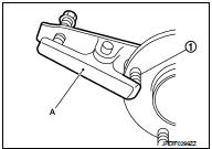
14. Remove hub bolts (1) from wheel hub assembly, using the ball joint remover (A) (commercial service tool).
CAUTION:
• Remove hub bolt only when necessary.
• Never hammer the hub bolt to avoid impact to the wheel hub assembly.
• Pull out the hub bolt in a direction perpendicular to the wheel hub assembly.
15. Perform inspection after removal. Refer to FAX-13, "Inspection".
INSTALLATION
Note the following, and install in the reverse order of the removal.
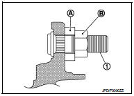
• Place a washer (A) as shown in the figure to install the hub bolts (1) by using the tightening force of the nut (B).
CAUTION:
• Check that there is no clearance between wheel hub assembly,
and hub bolt.
• Never reuse hub bolt.
• Never reuse steering knuckle and transverse link fixing nut.
• Clean the matching surface of wheel hub lock nut and wheel hub assembly.
CAUTION:
Never apply lubricating oil to these matching surface.
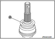
• Clean the matching surface of drive shaft, wheel hub assembly.
And then apply paste [service parts (440037S000)] to surface (A) of joint sub-assembly of drive shaft.
CAUTION:
Apply paste to cover entire flat surface of joint sub-assembly
of drive shaft.
Amount paste : 1.0 – 3.0 g (0.04 – 0.10 oz)
• Use the following torque range for tightening the wheel hub lock nut.
 : 180 – 185 N·m (18.4 – 18.8
kg-m, 133 – 136 ft-lb)
CAUTION:
• Since the drive shaft is assembled by press-fitting, use the tightening torque
range for the wheel
hub lock nut.
• Be sure to use torque wrench to tighten the wheel hub lock nut. Never use a power tool.
• Never reuse wheel hub lock nut.
NOTE:
Wheel hub lock nut tightening torque does not over torque for avoiding axle noise, and does not less than torque for avoiding looseness.
• Align the matching marks that have been made during removal when reusing the disc rotor.
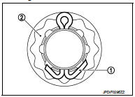
• When installing a cotter pin (1) and adjusting cap (2), securely bend the basal portion to prevent rattles.
CAUTION:
Never reuse cotter pin.
• Perform the final tightening of each of parts under unladen conditions, which were removed when removing wheel hub assembly and axle housing.
• Perform inspection after installation. Refer to FAX-13, "Inspection".
Inspection
INSPECTION AFTER REMOVAL
Check the following items, and replace the part if necessary.
• Check components for deformation, cracks, and other damage.
• Check boots of transverse link and steering outer socket ball joint for breakage, axial end play, and swing torque. Refer to FSU-14, "Inspection" and ST-21, "Inspection".
INSPECTION AFTER INSTALLATION
1. Check wheel sensor harness for proper connection. Refer to BRC-84, "FRONT WHEEL SENSOR : Exploded View" (Without ESP) or BRC-224, "FRONT WHEEL SENSOR : Exploded View" (With ESP).
2. Check the wheel alignment. Refer to FSU-7, "Inspection".

 Front drive shaft boot
Exploded View
LEFT SIDE
1. Circular clip
2. Dust shield
3. Housing assembly
4. Boot band
5. Boot
6. Damper band
7. Dynamic damper
8. Circular clip
9. Joint sub-assembly
: Wheel side ...
Other materials:
P0037, P0038 HO2S2 heater
DTC Logic
DTC DETECTION LOGIC
DTC CONFIRMATION PROCEDURE
1.PRECONDITIONING
If DTC Confirmation Procedure has been previously conducted, always perform
the following procedure before conducting the next test.
1. Turn ignition switch OFF and wait at least 10 seconds.
2. Turn ignition switc ...
Component parts
Component Parts Location
1. BCM
Refer to BCS-6, "BODY CONTROL
SYSTEM : Component Parts Location"
(With Intelligent Key system) or
BCS-96, "BODY CONTROL SYSTEM
: Component Parts Location"
(Without Intelligent Key system).
2. Rear window defogger connector
3. Rear windo ...
Immediate charge
When you haven't enabled a charging timer, your Nissan Leaf is designed to begin charging automatically the moment you connect a normal or trickle charge connector to the vehicle's charge port. This ensures the most straightforward and rapid replenishment of your battery.
However, even if you h ...
