Nissan Juke Service and Repair Manual : Front washer nozzle and tube
Exploded View
LHD models
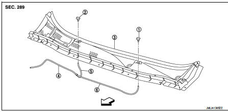
1. Front washer nozzle LH
2. Front washer nozzle RH
3. Cowl top cover
4. Front washer tube (tank side)
5. Front washer tube RH
6. Front washer tube LH
 : Vehicle front
Hydraulic Layout
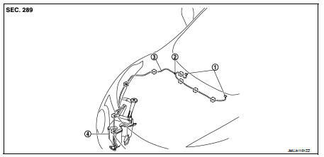
1. Front washer nozzle
2. Check valve
3. Front washer
4. Washer tank
 : Cli
: Cli
Removal and Installation
REMOVAL
1. Remove cowl top cover. Refer to EXT-20, "Removal and Installation".
2. Disconnect front washer tube from front washer nozzle.
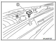
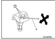
3. While pressing pawl (A) on the cowl top cover front side of front washer nozzle (1), remove front washer nozzle from cowl top cover.
INSTALLATION
Note the following item, and then install in the reverse order of removal.
CAUTION:
The spray positions differ, check that left and right nozzles are installed
correctly.
Inspection and Adjustment
INSPECTION
Check valve Inspection Check that air can pass through the hose by blowing forward (toward the nozzle (1)), and check that air cannot pass through by sucking.
ADJUSTMENT
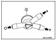
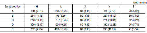
Washer Nozzle Spray Position Adjustment Adjust spray positions to match the positions shown in the figure.
LHD models
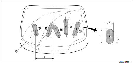
1. Black printed frame line
 : Spray area
 : Target spray position
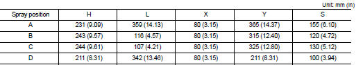
RHD models
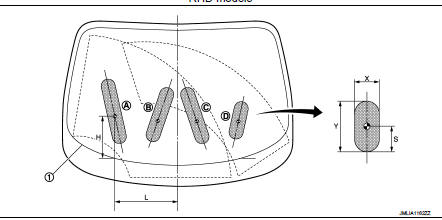
1. Black printed frame line
 : Spray area
 : Target spray position
Insert a needle or similar object (A) into the spray opening (1) and move up/down and left/right to adjust the spray position.
NOTE
:
If wax or dust gets into the nozzle, remove wax or dust with a needle
or small pin.
 Washer level switch
Removal and Installation
The washer level switch must be replaced together with the washer tank as an
assembly. Refer to WW-67,
"Removal and Installation". ...
 Front wiper arm
Exploded View
RHD models
1. Front wiper arm cap
2. Front wiper arm RH
3. Front wiper drive assembly
4. Front wiper motor
5. Front wiper blade LH
6. Front wiper arm LH
7. Front wiper blad ...
Other materials:
Steering Assist limitations
WARNING
In the following situations, the front-facing camera may fail to identify lane markers accurately or misinterpret road features, which may result in the Steering Assist system failing to operate as intended:
When navigating roads with confusing, ...
ANTI-HIJACK function does not operate
Diagnosis Procedure
1.CHECK “DOOR LOCK–UNLOCK SET” SETTING IN “WORK SUPPORT”
1. Select “DOOR LOCK” of “BCM” using CONSULT-III.
2. Select “DOOR LOCK-UNLOCK SET” in “WORK SUPPORT” mode.
3. Check “DOOR LOCK-UNLOCK SET” in “WORK SUPPORT”
Refer to DLK-371, "DOO ...
P0075 IVT control solenoid valve
DTC Logic
DTC DETECTION LOGIC
DTC CONFIRMATION PROCEDURE
1.PRECONDITIONING
If DTC Confirmation Procedure has been previously conducted, always perform
the following procedure
before conducting the next test.
1. Turn ignition switch OFF and wait at least 10 seconds.
2. Turn ignition swit ...
