Nissan Juke Service and Repair Manual : Evaporative emission system
Inspection
1. Visually inspect EVAP vapor lines for improper attachment and for cracks, damage, loose connections, chafing and deterioration.
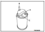
2. Check EVAP canister as follows: a. Block port (B). Orally blow air through port (A).
Check that air flows freely through port (C).
b. Block port (A). Orally blow air through port (B).
Check that air flows freely through port (C).
3. Visually inspect the fuel check valve for cracks, damage, loose connections chafing and deterioration.
4. Check fuel check valve as follows: a. Blow air through connector on the fuel tank side. A considerable resistance should be felt and a portion of air flow should be directed toward the EVAP canister side.
b. Blow air through connector on EVAP canister side. Air flow should be smoothly directed toward fuel tank side.
c. If fuel check valve is suspected or not properly functioning in step 1 and 2 above, replace it.
5. Inspect fuel tank filler cap vacuum relief valve for clogging, sticking, etc.
a. Wipe clean valve housing.
b. Check valve opening pressure and vacuum.
Pressure:
15.3 - 20.0 kPa (0.153 - 0.200 bar, 0.156 - 0.204 kg/
cm2, 2.22 - 2.90 psi)
Vacuum:
–6.0 to –3.4 kPa (–0.06 bar to –-0.034bar, –0.061 to –
0.035 kg/cm2, –0.87 to –0.49 psi)
c. If out of specification, replace fuel filler cap as an assembly
 Ignition timing
Description
This describes how to check the ignition timing. For the actual procedure,
follow the instructions in “BASIC
INSPECTION”.
Special Repair Requirement
1.CHECK IGNITION TIMING
1. A ...
 Positive crankcase ventilation
Inspection
1.CHECK PCV VALVE
With engine running at idle, remove PCV valve from rocker cover. A
properly working valve makes a hissing noise as air passes through
it. A strong vacuum should be fel ...
Other materials:
Back door request switch
Component Function Check
1.CHECK FUNCTION
1. Select “INTELLIGENT KEY” of “BCM” using CONSULT-III.
2. Select “REQ SW-BD/TR” in “DATA MONITOR” mode.
3. Check that the function operates normally according to the following
conditions.
Is the inspection result normal?
YES >&g ...
Sealant or/and Lubricant
HFC-134a (R-134a) Service Tool and Equipment
• Never mix HFC-134a (R-134a) refrigerant and/or its specified lubricant with
CFC-12 (R-12) refrigerant and/
or its lubricant.
• Separate and non-interchangeable service equipment must be used for handling
each type of refrigerant/
lubricant.
...
Inside mirror
Adjust the angle of the inside mirror to the desired position.
The night position1 will reduce glare from the headlights of vehicles behind
you at night.
Use the day position2 when driving in daylight hours.
WARNING
Use the night position only when necessary, because it reduces rear view c ...
