Nissan Juke Service and Repair Manual : Engine stand setting
Setting
NOTE
:
Explained here is how to disassemble with engine stand supporting transaxle
surface. When using different
type of engine stand, note with difference in steps and etc.
1. Remove the engine and the transaxle assembly from the vehicle, and separate the transaxle from the engine.
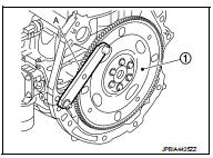
2. Install engine to engine stand with the following procedure: a. Remove flywheel (M/T models) or drive plate (CVT models).
ÔÇó Secure flywheel (M/T models) or drive plate (CVT models) (1) with a stopper plate [SST: KV11105210 (J-44716)] (A), and remove mounting bolts.
CAUTION:
ÔÇó Never disassemble them.
ÔÇó Never place them with signal plate facing down.
ÔÇó When handling signal plate, take care not to damage or scratch them.
ÔÇó Handle signal plate in a manner that prevents them from becoming magnetized.
NOTE
:
This figure shows CVT models as an example.
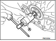
b. Remove pilot converter (1) using pilot bushing puller [SST: ST16610001 (J-23907)] (A) or suitable tool. (CVT models) NOTE
:
M/T models have no pilot bushing.
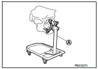
c. Lift the engine with a hoist to install it onto widely use engine stand.
CAUTION:
ÔÇó Use the engine stand that has a load capacity [approximately 135 kg (298 lb)
or more] large
enough for supporting the engine weight.
ÔÇó If the load capacity of stand is not adequate, remove the following parts beforehand to reduce the potential risk of overturning stand.
- Intake manifold: Refer to EM-28, "Exploded View".
- catalyst convertor: Refer to EM-33, "2WD : Exploded View" (2WD models) or EM-34, "4WD : Exploded View" (4WD models).
- Rocker cover: Refer to EM-53, "Exploded View".
NOTE:
The figure shows an example of widely used engine stand (A) that can support mating surface of transaxle with flywheel (M/T models) or drive plate (CVT models) removed.
CAUTION:
Before removing the hanging chains, check the engine
stand is stable and there is no risk of overturning.
3. Drain engine oil. Refer to LU-9, "Draining".
CAUTION:
Be sure to clean drain plug and install with new drain plug washer.
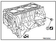
4. Drain engine coolant by removing water drain plug (1) from inside of the engine.
 : Engine front
Tightening torque : Refer to EM-104, "Disassembly and Assembly".
Use Genuine Liquid Gasket or equivalent.

 Engine unit
Disassembly
1. Remove intake manifold. Refer to EM-28, "Exploded View".
2. Remove catalyst convertor. Refer to EM-33, "2WD : Exploded View" (2WD models)
or EM-34, "4WD :
...
Other materials:
Door motor
Diagnosis Procedure
NOTE:
If all of door motor DTCs are detected, check this circuit.
1.CHECK DOOR MOTOR POWER SUPPLY
1. Turn ignition switch ON.
2. Check voltage between intake door motor harness connector and ground.
Is the inspection result normal?
YES >> GO TO 2.
NO >> ...
P0237, P0238 TC boost sensor
DTC Logic
DTC DETECTION LOGIC
DTC CONFIRMATION PROCEDURE
1.PRECONDITIONING
If DTC Confirmation Procedure has been previously conducted, always perform
the following procedure
before conducting the next test.
1. Turn ignition switch OFF and wait at least 10 seconds.
2. Turn ignition swit ...
Precaution for Supplemental Restraint System (SRS) "AIR BAG" and "SEAT BELT
PRE-TENSIONER"
The Supplemental Restraint System such as ÔÇťAIR BAGÔÇŁ and ÔÇťSEAT BELT PRE-TENSIONERÔÇŁ,
used along
with a front seat belt, helps to reduce the risk or severity of injury to the
driver and front passenger for certain
types of collision. Information necessary to service the system safely is
...
