Nissan Juke Service and Repair Manual : Engine maintenance (HR16DE)
Drive belt
DRIVE BELT : Checking
ÔÇó Inspection should be done only when engine is cold or over 30 minutes after the engine is stopped.
1 : Alternator
2 : Water pump
3 : Crankshaft pulley
4 : A/C compressor
5 : Idler pulley
6 : Drive belt
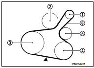
ÔÇó Visually check belts for wear, damage, and cracks on inside and edges.
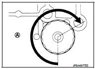
ÔÇó Turn crankshaft pulley two time clockwise, and check tension on all pulleys is equal before doing the test.
ÔÇó When measuring deflection, apply 98 N (10 kg, 22 lb) at the (
 ) marked point.
ÔÇó Measure the belt tension and frequency with acoustic tension gauge (commercial
service tool) at the ( )
)
marked point.
CAUTION:
ÔÇó When the tension and frequency are measured, the acoustic tension gauge should
be used.
ÔÇó When checking immediately after installation, first adjust it to the specified value. Then, after turning crankshaft two turns or more, readjust to the specified value to avoid variation in deflection between pulleys.
Belt Deflection/Belt Tension and Frequency: Refer to EM-250, "Drive Belt".
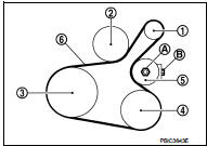
DRIVE BELT : Tension Adjustment

CAUTION:
ÔÇó When belt is replaced with new one, adjust belt tension to the value for ÔÇťNew
beltÔÇŁ, because new belt
will not fully seat in the pulley groove.
ÔÇó When tension of the belt being used exceeds ÔÇťLimitÔÇŁ, adjust it to the value for ÔÇťAfter adjustedÔÇŁ.
ÔÇó When installing a belt, check it is correctly engaged with the pulley groove.
ÔÇó Never allow oil or engine coolant to get on the belt.
ÔÇó Never twist or bend the belt strongly.
1. Remove front fender protector (RH). Refer to EXT-22, "Exploded View".
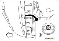
2. After loosening lock nut (A) of idler pulley (5) to release from the specified torque state, temporarily tighten the lock nut to the following torque
 4.4 N┬Ěm (0.45 kg-m, 39 in-lb)
1 : Alternator
2 : Water pump
3 : Crankshaft pulley
4 : A/C compressor
5 : Idler pulley
6 : Drive belt
CAUTION
ÔÇó When the lock nut is loosened excessively, the idler pulley tilts and the
correct tension adjustment
cannot be performed. Never loosen it excessively (more than 45 degrees).
ÔÇó Put a matching mark on the lock nut (A), and check turning angle with a protractor. Never visually check the tightening angle.
3. Adjust the belt tension by turning the adjusting bolt (B). Refer to MA-24, "DRIVE BELT : Checking".
CAUTION:
ÔÇó When checking immediately after installation, first adjust it to the specified
value. Then, after
turning crankshaft two turns or more, readjust to the specified value to avoid
variation in deflection
between pulleys.
ÔÇó When the tension adjustment is performed, the lock nut should be in the condition at stepÔÇť 2ÔÇŁ. If the tension adjustment is performed when the lock nut is loosened more than the standard, the idler pulley tilts and the correct tension adjustment cannot be performed.
4. Tighten the lock nut.
 : 34.8 N┬Ěm (3.5 kg-m, 26 ft-lb)
Engine coolant
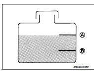
ENGINE COOLANT : Inspection
LEVEL
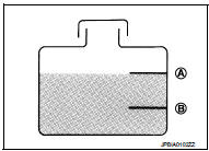
ÔÇó Check that the reservoir tank engine coolant level is within the ÔÇťMINÔÇŁ to ÔÇťMAXÔÇŁ when the engine is cool.
A : MAX
B : MIN
ÔÇó Adjust the engine coolant level if necessary.
LEAKAGE
ÔÇó To check for leakage, apply pressure to the cooling system with the radiator cap tester (commercial service tool) (A) and the radiator cap tester adapter (commercial service tool) (B).
Testing pressure: Refer to CO-54, "Radiator".
WARNING:
Never remove radiator cap when engine is hot. Serious burns
may occur from high-pressure engine coolant escaping from
radiator.
CAUTION:
Higher test pressure than specified may cause radiator damage.
NOTE:
In a case that engine coolant decreases, replenish radiator with engine coolant.
ÔÇó If anything is found, repair or replace damaged parts.
ENGINE COOLANT : Draining
WARNING:
ÔÇó Never remove radiator cap when engine is hot. Serious burns may occur from
high-pressure engine
coolant escaping from radiator.
ÔÇó Wrap a thick cloth around the radiator cap. Slowly turn it a quarter of a turn to release built-up pressure.
Then turn it all the way.
1. Remove engine under cover.
2. Open radiator drain plug (A) at the bottom of radiator, and then remove radiator cap.
 : Vehicle front
CAUTION:
Perform this step when engine is cold.
ÔÇó When draining all of engine coolant in the system, open water drain plugs on cylinder block. Refer to EM-228, "Disassembly and Assembly".
3. Remove reservoir tank if necessary, and drain engine coolant and clean reservoir tank before installing.
Refer to CO-42, "Exploded View".
4. Check drained engine coolant for contaminants such as rust, corrosion or discoloration. If contaminated, flush the engine cooling system. Refer to MA-27, "ENGINE COOLANT : Flushing".
ENGINE COOLANT : Refilling
1. Install reservoir tank if removed and radiator drain plug.
CAUTION:
Be sure to clean drain plug and install with new O-ring.
Radiator drain plug : Refer to CO-42, "Exploded View".
ÔÇó If water drain plugs on cylinder block are removed, close and tighten them. Refer to EM-228, "Disassembly and Assembly".
2. Check that each hose clamp has been firmly tightened.
3. Remove air duct (between air cleaner case and electric throttle control actuator). Refer to EM-161, "Exploded View".
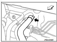
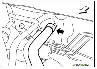
4. Disconnect heater hose (1) at position (
) in the figure.
 : Vehicle front
ÔÇó Enhance heater hose as high as possible.
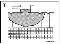
5. Fill radiator (1) to specified level.
CAUTION:
Never adhere the engine coolant to electronic equipments
(alternator etc.).
ÔÇó Pour coolant slowly of less than 2 (2-1/8 US qt, 1-3/4 Imp qt) a minute to allow air in system to escape.
ÔÇó When engine coolant overflows disconnected heater hose, connect heater hose, and continue filling the engine coolant.
ÔÇó Use Genuine NISSAN Engine Coolant or equivalent in its quality mixed with water (distilled or demineralized). Refer to MA-13, "Fluids and Lubricants".
Engine coolant capacity (With reservoir tank at ÔÇťMAXÔÇŁ level) Refer to CO-54, "Periodical Maintenance Specification".
6. Refill reservoir tank to ÔÇťMAXÔÇŁ level line with engine coolant.
A : MAX
B : MIN
Reservoir tank engine coolant capacity
(At ÔÇťMAXÔÇŁ level)
Refer to CO-54, "Periodical Maintenance Specification".
7. Install air duct (between air cleaner case and electric throttle control actuator). Refer to EM-161, "Exploded View".
8. Install radiator cap.
9. Warm up engine until opening thermostat. Standard for warming-up time is approximately 10 minutes at 3,000 rpm.
ÔÇó Check thermostat opening condition by touching radiator hose (lower) to see a flow of warm water.
CAUTION:
Watch water temperature gauge so as not to overheat engine.
10. Stop the engine and cool down to less than approximately 50┬░C (122┬░F).
ÔÇó Cool down using fan to reduce the time.
ÔÇó If necessary, refill radiator up to filler neck with engine coolant.
CAUTION:
Never adhere the engine coolant to electronic equipments (alternator etc.).
11. Refill reservoir tank to ÔÇťMAXÔÇŁ level line with engine coolant.
12. Repeat steps 5 through 10 two or more times with radiator cap installed until engine coolant level no longer drops.
13. Check cooling system for leakage with engine running.
14. Warm up the engine, and check for sound of engine coolant flow while running engine from idle up to 3,000 rpm with heater temperature controller set at several position between ÔÇťCOOLÔÇŁ and ÔÇťWARMÔÇŁ.
ÔÇó Sound may be noticeable at heater unit.
15. Repeat step 14 three times.
16. If sound is heard, bleed air from cooling system by repeating step 5 through 10 until reservoir tank level no longer drops.
ENGINE COOLANT : Flushing
1. Install reservoir tank if removed and radiator drain plug.
CAUTION:
Be sure to clean drain plug and install with new O-ring.
Radiator drain plug : Refer to CO-42, "Exploded View".
ÔÇó If water drain plugs on cylinder block are removed, close and tighten them. Refer to EM-228, "Disassembly and Assembly".
2. EM-161, "Exploded View"Remove air duct (between air cleaner case and electric throttle control actuator).
Refer to .
3. Disconnect heater hose (1) at position (
) in the figure.
 : Vehicle front
ÔÇó Enhance heater as high as possible.
4. Fill radiator and reservoir tank with water and reinstall radiator cap.
ÔÇó When engine coolant over flows disconnected heater hose, connect heater hose, and continue filling the engine coolant.
5. Install air duct (between air cleaner case and electric throttle control actuator). Refer to EM-161, "Exploded View".
6. Run the engine and warm it up to normal operating temperature.
7. Rev the engine two or three times under no-load.
8. Stop the engine and wait until it cools down.
9. Drain water from the system. Refer to MA-25, "ENGINE COOLANT : Draining".
10. Repeat steps 1 through 9 until clear water begins to drain from radiator.
Radiator cap
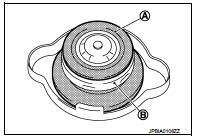
RADIATOR CAP : Inspection
ÔÇó Check valve seat (A) of radiator cap.
B : Metal plunger
- Check that valve seat is swollen to the extent that the edge of the plunger cannot be seen when watching it vertically from the top.
- Check that valve seat has no soil and damage.
ÔÇó Pull negative-pressure valve to open it, and that it close completely when released.
- Check that there is no dirt or damage on the valve seat of radiator cap negative-pressure valve.
- Check that there are no unusualness in the opening and closing conditions of negative-pressure valve.
ÔÇó Check radiator cap relief pressure.
Standard and Limit : Refer to CO-54, "Radiator".
- When connecting radiator cap to the radiator cap tester (commercial service tool) (A) and the radiator cap tester adapter (commercial service tool) (B), apply engine coolant to the cap seal surface.
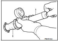
ÔÇó Replace radiator cap if there is an unusualness related to the above three.
CAUTION:
When installing radiator cap, thoroughly wipe out the radiator filler neck to
remove any waxy residue
or foreign material.
Radiator
RADIATOR : Inspection
Check radiator for mud or clogging. If necessary, clean radiator as follows.
CAUTION:
ÔÇó Be careful not to bend or damage radiator fins.
ÔÇó When radiator is cleaned without removal, remove all surrounding parts such as radiator cooling fan assembly and horns. Then tape harness and harness connectors to prevent water from entering.
1. Apply water by hose to the back side of the radiator core vertically downward.
2. Apply water again to all radiator core surfaces once per minute.
3. Stop washing if any stains no longer flow out from radiator.
4. Blow air into the back side of radiator core vertically downward.
ÔÇó Use compressed air lower than 490 kPa (4.9 bar, 5 kg/cm2, 71 psi) and keep distance more than 30 cm (11.81 in).
5. Blow air again into all the radiator core surfaces once per minute until no water sprays out.
Fuel lines
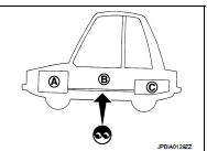
FUEL LINES : Inspection
Inspect fuel lines, fuel filler cap, and fuel tank for improper attachment, leakage, cracks, damage, loose connections, chafing or deterioration.
A : Engine
B : Fuel line
C : Fuel tank
If necessary, repair or replace damaged parts.
Air cleaner filter
AIR CLEANER FILTER : Removal and Installation
REMOVAL
1. Remove the assembly consisting of element case, air cleaner case, and inlet air duct (upper).
2. Remove the air cleaner filter case.
3. Remove the air cleaner filter (2) from the air cleaner case (1).
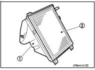
INSTALLATION
Note the following, and install in the reverse order of removal.
ÔÇó Check by the feel and the sound that both pawls of the air cleaner case are securely fastened to the element case.
Engine oil
ENGINE OIL : Draining
WARNING:
ÔÇó Be careful not to get burned, as engine oil may be hot.
ÔÇó Prolonged and repeated contact with used engine oil may cause skin cancer. Try to avoid direct skin contact with used engine oil. If skin contact is made, wash thoroughly with soap or hand cleaner as soon as possible.
1. Warm up the engine, and check for engine oil leakage from engine components. Refer to LU-25, "Inspection".
2. Stop the engine and wait for 10 minutes.
3. Loosen oil filler cap.
4. Remove drain plug and then drain engine oil.
ENGINE OIL : Refilling
1. Install drain plug with new drain plug washer. Refer to EM-169, "Exploded View".
CAUTION:
Be sure to clean drain plug and install with new drain plug washer.
Tightening torque : Refer to EM-169, "Exploded View".
2. Refill with new engine oil.
Engine oil specification and viscosity: Refer to MA-13, "Fluids and Lubricants".
Engine oil capacity : Refer to LU-29, "Periodical Maintenance Specification".
CAUTION:
ÔÇó The refill capacity depends on the engine oil temperature and drain time. Use
these specifications
for reference only.
ÔÇó Always use oil level gauge to determine the proper amount of engine oil in the engine.
3. Warm up engine and check area around drain plug and oil filter for engine oil leakage.
4. Stop engine and wait for 10 minutes.
5. Check the engine oil level. Refer to LU-25, "Inspection".
Oil filter
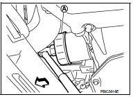
OIL FILTER : Removal and Installation
REMOVAL
1. Remove engine under cover.
2. Using oil filter wrench [SST: KV10115801] (A), remove oil filter.
 : Vehicle front
CAUTION:
ÔÇó Oil filter is provided with relief valve. Use genuine NISSAN
oil filter or equivalent.
ÔÇó Be careful not to get burned when engine and engine oil may be hot.
ÔÇó When removing, prepare a shop cloth to absorb any engine oil leakage or spillage.
ÔÇó Completely wipe off any engine oil that adheres to engine and vehicle.
INSTALLATION
1. Remove foreign materials adhering to the oil filter installation surface.
2. Apply new engine oil to the oil seal contact surface of new oil filter.
3. Screw oil filter manually until it touches the installation surface, then tighten it by 2/3 turn (A). Or tighten to specification.
Oil filter:
 : 17.7 N┬Ěm (1.8 kg-m, 13 ft-lb)
OIL FILTER : Inspection
INSPECTION AFTER INSTALLATION
1. Check the engine oil level. Refer to LU-25, "Inspection".
2. Start the engine, and check that there is no leakage of engine oil.
3. Stop the engine and wait for 10 minutes.
4. Check the engine oil level, and adjust the level. Refer to LU-25, "Inspection".
Spark plug
SPARK PLUG : Removal and Installation
REMOVAL
1. Remove ignition coil. Refer to EM-178, "Exploded View".
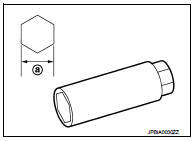
2. Remove spark plug with a spark plug wrench (commercial service tool).
a : 14 mm (0.55 in)
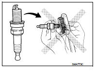
CAUTION:
Never drop or shock spark plug.
INSTALLATION
Install in the reverse order of removal.
SPARK PLUG : Inspection
INSPECTION AFTER REMOVAL
Use the standard type spark plug for normal condition.
Spark plug (Standard type) : Refer to EM-251, "Spark Plug".
CAUTION:
ÔÇó Never drop or shock spark plug.
ÔÇó Never use a wire brush for cleaning.
ÔÇó If plug tip is covered with carbon, spark plug cleaner may be used.
Cleaner air pressure : Less than 588 kPa (6 kg/cm2,
85 psi)
Cleaning time : Less than 20 seconds
Evap vapor lines
EVAP VAPOR LINES : Inspection
1. Visually inspect EVAP vapor lines for improper attachment and for cracks, damage, loose connections, chafing and deterioration.
2. Inspect fuel tank filler cap vacuum relief valve for clogging, sticking, etc.
Refer to EC-803, "Inspection".
 Engine maintenance (MR16DDT)
Drive belt
DRIVE BELT : Exploded View
1. Alternator
2. Drive belt auto-tensioner
3. Crankshaft pulley
4. A/C compressor
5. Water pump
6. Drive belt
A. Possible use range
B.
Range when ...
 Engine maintenance (K9K)
Drive belt
DRIVE BELT : Checking Drive Belts
WARNING:
Be sure to perform when the engine is stopped.
1. Inspect belts for cracks, fraying, wear and oil. If necessary,
replace.
2. Evaluate manu ...
Other materials:
Remove
Use the following procedure to remove the head restraint/headrest.
1. Pull the head restraint/headrest up to the highest position.
2. Push and hold the lock knob.
3. Remove the head restraint/headrest from the seat.
4. Store the head restraint/headrest properly in a secure place so it is not l ...
Structure and operation
Positive Crankcase Ventilation
This system returns blow-by gas to the intake manifold.
The positive crankcase ventilation (PCV) valve is provided to conduct crankcase
blow-by gas to the intake
manifold.
During partial throttle operation of the engine, the intake manifold sucks the
blow ...
ECM branch line circuit
Diagnosis Procedure
1.CHECK CONNECTOR
1. Turn the ignition switch OFF.
2. Disconnect the battery cable from the negative terminal.
3. Check the terminals and connectors of the ECM for damage, bend and loose
connection (unit side and
connector side).
Is the inspection result normal?
YES &g ...
