Nissan Juke Service and Repair Manual : Engine control system
Symptom Table
SYSTEM — BASIC ENGINE CONTROL SYSTEM

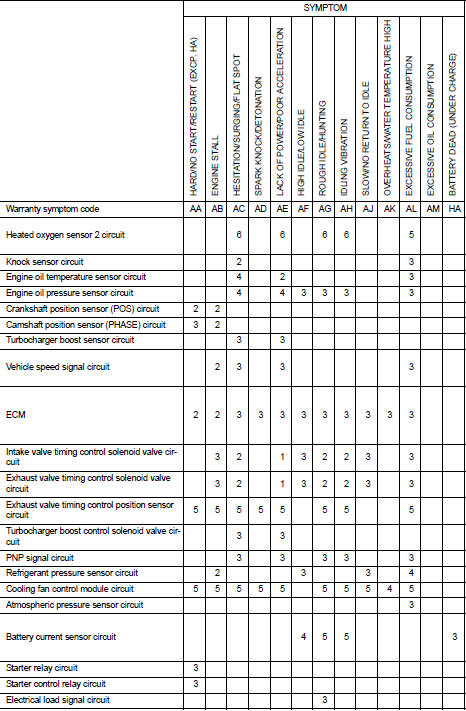
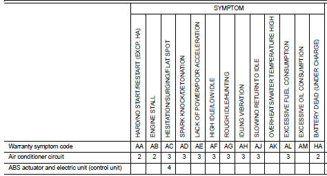
1 - 6: The numbers refer to the order of inspection.
(continued on next page)
SYSTEM — ENGINE MECHANICAL & OTHER
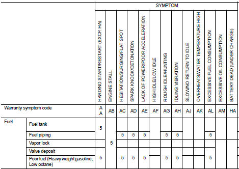
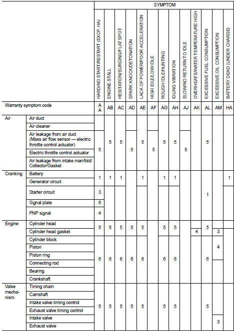
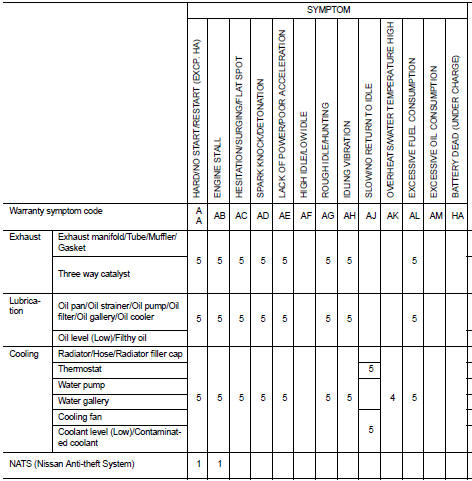
1 - 6: The numbers refer to the order of inspection.

 Normal operating condition
Description
FUEL CUT CONTROL (AT NO LOAD AND HIGH ENGINE SPEED)
If the engine speed is above 1,800 rpm under no load (for example, the
selector lever position is neutral and
engine speed is over ...
Other materials:
Keys
A key number plate is supplied with your keys.
Record the key number and keep it in a safe place (such as your wallet), not
in the vehicle. If you lose your keys, see a NISSAN dealer for duplicates by using
the key number. NISSAN does not record any key numbers so it is very important to
keep ...
Symptom diagnosis
CVT CONTROL SYSTEM
Symptom Table
The diagnosis item number indicates the order of check. Start checking in the
order from 1.
...
Rear door
Exploded View
1. Rear door panel
2. Door hinge (upper)
3. Door hinge (lower)
4. Door check link
5. Door striker
6. TORX bolt
: Do not reuse
: N·m (kg-m, in-lb)
: N·m (kg-m, ft-lb)
: Body grease
DOOR ASSEMBLY
DOOR ASSEMBLY : Removal and Installation
CAUTION:
• Perform work wit ...
