Nissan Juke Service and Repair Manual : Ecu diagnosis information
BCM (body control module)
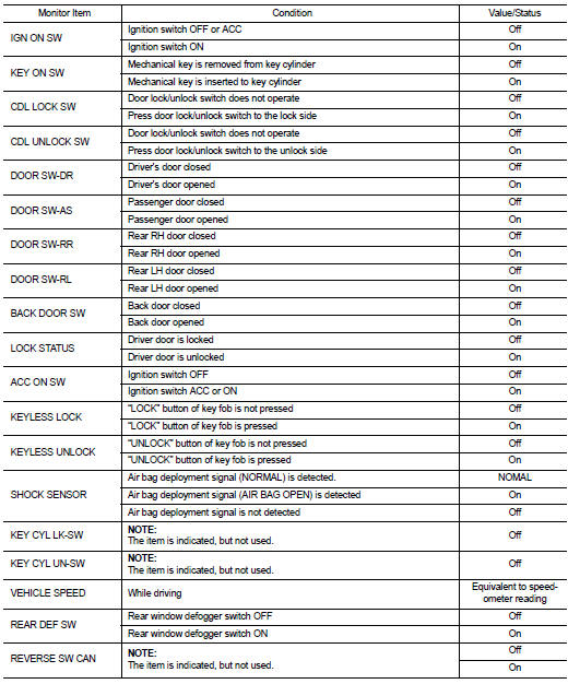
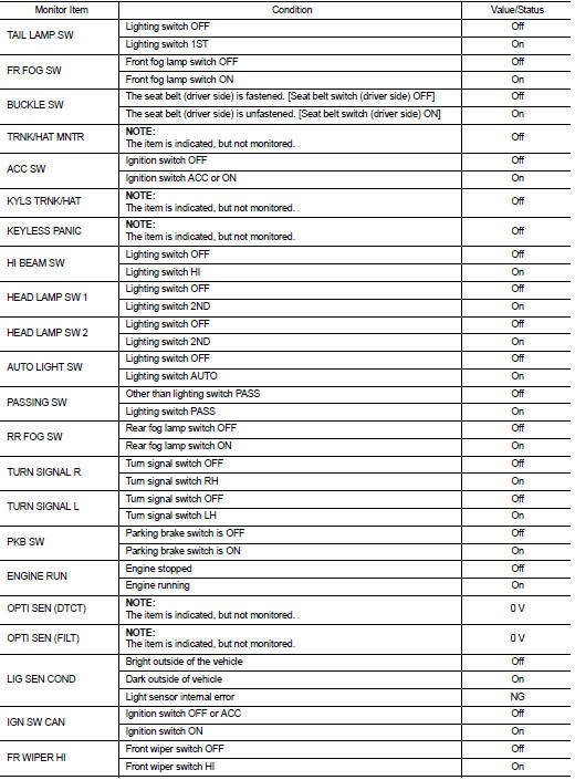
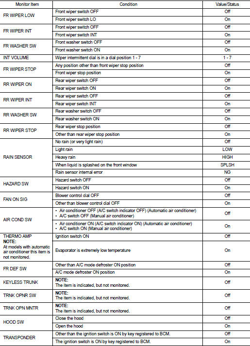
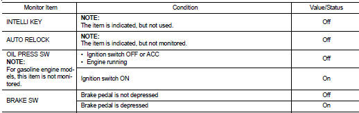
Reference Value
VALUES ON THE DIAGNOSIS TOOL
TERMINAL LAYOUT
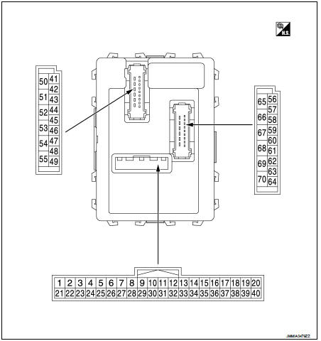
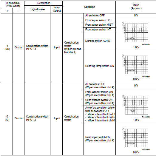
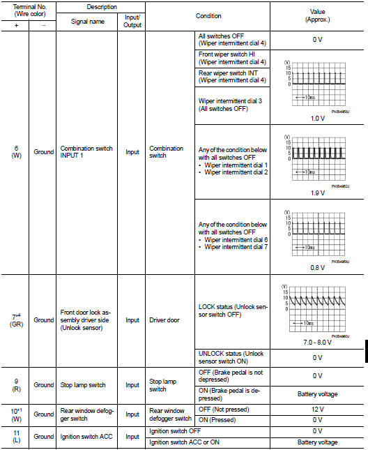
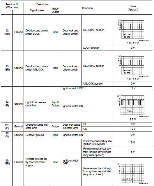
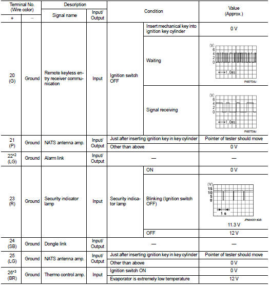
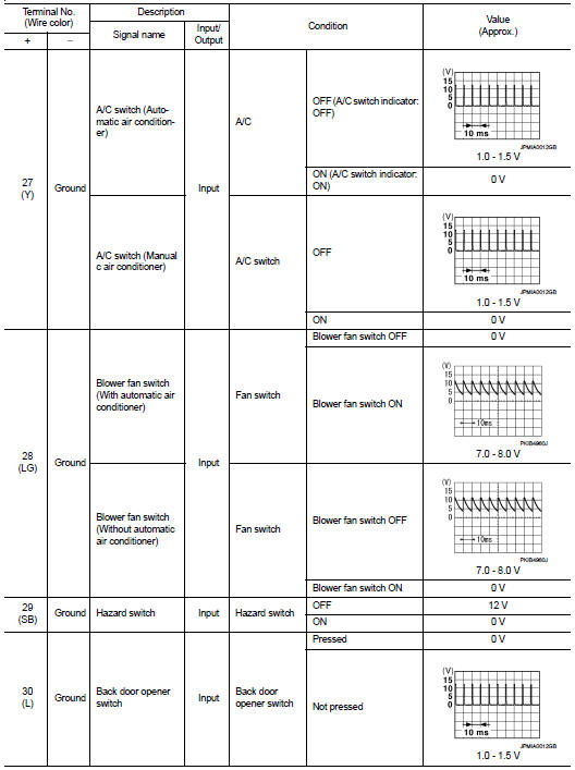
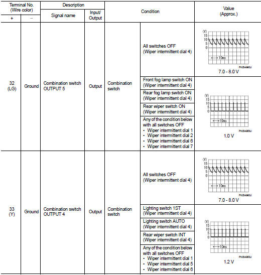
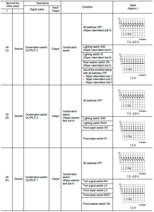
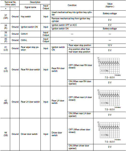
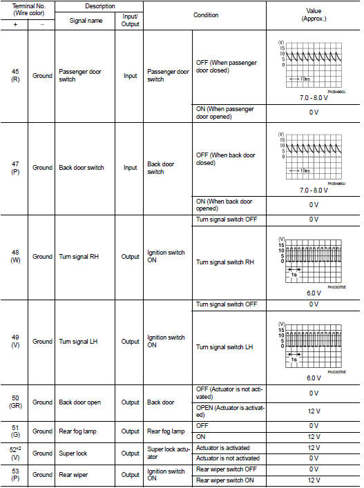
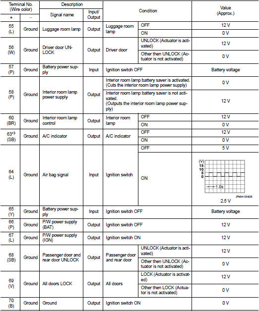
PHYSICAL VALUES
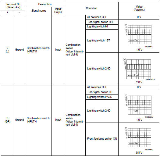
NOTE
:
• *1: Without automatic A/C
• *2: RHD models
• *3: With manual A/C
• *4: LHD models
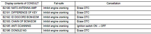
Fail-safe
FAIL-SAFE CONTROL BY DTC
BCM performs fail-safe control when any DTC are detected.
FAIL-SAFE CONTROL BY LIGHT AND RAIN SENSOR MALFUNCTION
BCM detects the light and rain sensor serial link error and the light and rain sensor malfunction.
BCM controls the following fail-safe when light and rain sensor has a malfunction.
Fail-safe Control
• Auto light control: Headlamp low beam, parking lamp, license plate lamp and
tail lamp are turned ON.
• Front wiper control
- Front wiper switch AUTO and sensing rain drop: The condition just before the
activation of fail-safe is maintained
until the front wiper switch is turned OFF.
- Front wiper switch AUTO and not sensing rain drop: Front wiper is LO operation until the front wiper switch is turned off.
REAR WIPER MOTOR PROTECTION
BCM detects the rear wiper stopping position according to the rear wiper auto stop signal.
When the rear wiper auto stop signal does not change more than 5 seconds while driving the rear wiper, BCM stops power supply to protect the rear wiper motor.
Condition of cancellation 1. Pass more than 1 minute after the rear wiper stop.
2. Turn rear wiper switch OFF.
3. Operate the rear wiper switch or rear washer switch.
FAIL-SAFE CONTROL OF COMBINATION SWITCH READING FUNCTION CAUSED BY LOW POWER SUPPLY VOLTAGE
If voltage of battery power supply lower, BCM maintains combination switch reading to the status when input voltage is less than approximately 9 V.
NOTE
:
When voltage of battery power supply is approximately 9 V or more, combination
switch reading function
returns to normal operation.
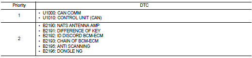
DTC Inspection Priority Chart
If some DTCs are displayed at the same time, perform inspections one by one based on the following priority chart.
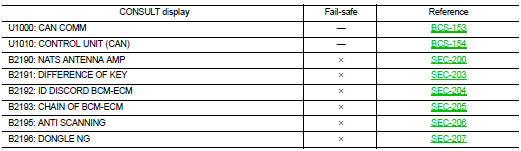
DTC Index
NOTE
:
Details of time display
• CRNT: Displays when there is a malfunction now or after returning to the
normal condition until turning ignition
switch OFF → ON again.
‚Ä¢ 1 - 39: Displayed if any previous malfunction is present when current condition is normal. It increases like 1 → 2 → 3...38 → 39 after returning to the normal condition whenever ignition switch OFF → ON. The counter remains at 39 even if the number of cycles exceeds it. It is counted from 1 again when turning ignition switch OFF → ON after returning to the normal condition if the malfunction is detected again.
 Diagnosis system (BCM)
Common item
COMMON ITEM : CONSULT-III Function (BCM - COMMON ITEM)
APPLICATION ITEM
CONSULT-III performs the following functions via CAN communication with BCM.
SYSTEM APPLICATION
BCM can perfo ...
 Wiring diagram
...
Other materials:
U1000 can comm circuit
Description
CAN (Controller Area Network) is a serial communication line for real time
application. It is an on-vehicle multiplex
communication line with high data communication speed and excellent error
detection ability. Many electronic
control units are equipped onto a vehicle, and each co ...
Precautions For Refrigerant System Service
GENERAL REFRIGERANT PRECAUTION
WARNING:
• Never breathe A/C refrigerant and lubricant vapor or mist. Exposure may
irritate eyes, nose and
throat. Use only approved recovery/recycling equipment to discharge HFC-134a
(R-134a) refrigerant.
Ventilate work area before resuming service if acci ...
B1087 seat belt Pre-tensioner LH
DTC Logic
DTC DETECTION LOGIC
DTC CONFIRMATION PROCEDURE
1.CHECK SELF-DIAG RESULT
With CONSULT-III
1. Turn ignition switch ON.
2. Perform “Self Diagnostic Result” mode of “AIR BAG” using CONSULT-III.
Without CONSULT-III
1. Turn ignition switch ON.
2. Check the air bag warning la ...
