Nissan Juke Service and Repair Manual : Diagnosis and repair workflow
Work Flow
INTRODUCTION
The TCM receives a signal from the vehicle speed sensor, transmission range switch and provides shift control or lock-up control via CVT solenoid valves.
The TCM also communicates with the ECM by means of a signal sent from sensing elements used with the OBD-related parts of the CVT system for malfunction-diagnostic purposes. The TCM is capable of diagnosing malfunctioning parts while the ECM can store malfunctions in its memory.
Input and output signals must always be correct and stable in the operation of the CVT system. The CVT system must be in good operating condition and be free of valve seizure, solenoid valve malfunction, etc.
It is much more difficult to diagnose an error that occurs intermittently rather than continuously. Most intermittent errors are caused by poor electric connections or improper wiring. In this case, careful checking of suspected circuits may help prevent the replacement of good parts.
A visual check only may not find the cause of the errors. A road test with CONSULT-III (or GST) or a circuit tester connected should be performed. Follow the ÔÇťDETAILED FLOWÔÇŁ.
Before undertaking actual checks, take a few minutes to talk with a customer who approaches with a driveability complaint. The customer can supply good information about such errors, especially intermittent ones. Find out what symptoms are present and under what conditions they occur. A ÔÇťDiagnostic Work SheetÔÇŁ as shown on the example (Refer to TM-176) should be used.
Start your diagnosis by looking for ÔÇťconventionalÔÇŁ errors first. This will help troubleshoot driveability errors on an electronically controlled engine vehicle.
Also check related Service bulletins.
DETAILED FLOW
1.COLLECT THE INFORMATION FROM THE CUSTOMER
Get the detailed information from the customer about the symptom (the condition and the environment when the incident/malfunction occurred) using diagnosis worksheet. Refer to TM-176, "Diagnostic Work Sheet".
>> GO TO 2.
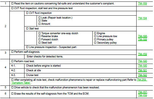
2.CHECK SYMPTOM 1
Check the following items based on the information obtained from the customer.
ÔÇó Fail-safe. Refer to TM-169, "Fail-safe".
ÔÇó CVT fluid inspection. Refer to TM-184, "Inspection".
ÔÇó Line pressure test. Refer to TM-188, "Inspection and Judgment".
ÔÇó Stall test. Refer to TM-186, "Inspection and Judgment".
>> GO TO 3.
3.CHECK DTC
1. Check DTC.
2. Perform the following procedure if DTC is detected.
ÔÇó Record DTC.
ÔÇó Erase DTC. Refer to TM-157, "Diagnosis Description".
Is any DTC detected? YES >> GO TO 4.
NO >> GO TO 5.
4.PERFORM DIAGNOSTIC PROCEDURE
Perform ÔÇťDiagnostic ProcedureÔÇŁ for the displayed DTC.
>> GO TO 5.
5.PERFORM DTC CONFIRMATION PROCEDURE
Perform ÔÇťDTC CONFIRMATIOM PROCEDUREÔÇŁ for the displayed DTC.
Is DTC detected? YES >> GO TO 4.
NO >> GO TO 6.
6.CHECK SYMPTOM 2
Confirm the symptom described by the customer.
Is any malfunction present? YES >> GO TO 7.
NO >> INSPECTION END
7.RODE TEST
Perform ÔÇťRODE TESTÔÇŁ. Refer to TM-190, "Description".
>> GO TO 8.
8.CHECK SYMPTOM 3
Confirm the symptom described by the customer.
Is any malfunction present? YES >> GO TO 2.
NO >> INSPECTION END
Diagnostic Work
INFORMATION FROM CUSTOMER
KEY POINTS
ÔÇó WHAT..... Vehicle & CVT model ÔÇó WHEN..... Date, Frequencies ÔÇó WHERE..... Road conditions ÔÇó HOW..... Operating conditions, Symptoms
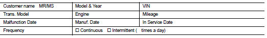
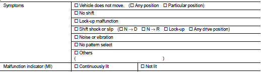
DIAGNOSTIC WORKSHEET
 Basic inspection
...
 Additional service when replacing TCM
Description
Always perform the following items when the TCM is replaced.
CHECK LOADING OF CALIBRATION DATA
ÔÇó The TCM acquires calibration data (individual characteristic value) of each
solenoid ...
Other materials:
Power steering system
WARNING
If the READY to drive indicator light is off while the vehicle is in motion, the electric power assist for the steering will not be active, making the steering wheel significantly heavier and harder to operate.
If the power steering warning light illuminates while you ...
System temporarily unavailable
In certain operational scenarios, the Intelligent Blind Spot Intervention (I-BSI) system in your Nissan Leaf may automatically deactivate to ensure safety. In these instances, you will hear an audible chime, and a specific warning message will appear on the vehicle information display, signaling tha ...
Component parts
CVT control system : Component Parts Location
1. Multi display unit (MDU)*
Refer to DMS-3, "Component Parts
Location".
2. Combination meter 3. S mode indicator
(On the combination meter)
4. Shift position indicator
(On the combination meter)
5. Malfunction indicator lamp (MIL)
( ...
